


Available from:
Itead.cc
Aliexpress.com
Domadoo.fr
Banggood.com
Amazon.com
Manufacturer:
Sonoff.tech
Install method:
USB to Serial
| GPIO # | Component |
|---|---|
| GPIO00 | Button 1 |
| GPIO01 | None |
| GPIO02 | None |
| GPIO03 | None |
| GPIO04 | None |
| GPIO05 | None |
| GPIO09 | None |
| GPIO10 | None |
| GPIO12 | None |
| GPIO13 | LedLinki |
| GPIO14 | Relay 2 |
| GPIO15 | None |
| GPIO16 | None |
| GPIO17 | None |
| GPIO18 | None |
| GPIO19 | None |
| GPIO20 | None |
| GPIO21 | None |
| GPIO22 | None |
| GPIO23 | None |
| GPIO24 | None |
| GPIO25 | Serial Tx |
| GPIO26 | BL0939 Rx |
| GPIO27 | Relay 1 |
| GPIO6 | None |
| GPIO7 | None |
| GPIO8 | None |
| GPIO11 | None |
| GPIO32 | Switch 1 |
| GPIO33 | Switch 2 |
| GPIO34 | None |
| GPIO35 | None |
| GPIO36 | None |
| GPIO37 | None |
| GPIO38 | None |
| GPIO39 | None |
{"NAME":"Sonoff Dual R3 v2","GPIO":[32,0,0,0,0,0,0,0,0,576,225,0,0,0,0,0,0,0,0,0,0,3200,8128,224,0,0,0,0,160,161,0,0,0,0,0,0],"FLAG":0,"BASE":1}Use code
BLAKADDER when buying from itead.cc for a 10% discount.
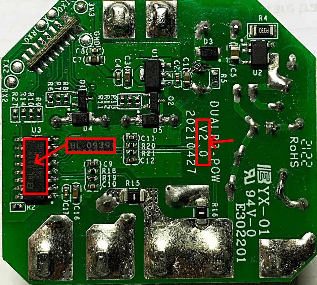
How to identify Sonoff Dual R3 v2
Starting September 2021, Sonoff started to distribute a new version with a different energy monitoring chip (BL0930 instead of CSE7761). There is no functional difference between v1.x and v2. This new model is supported since Tasmota32 v9.5.0.8.
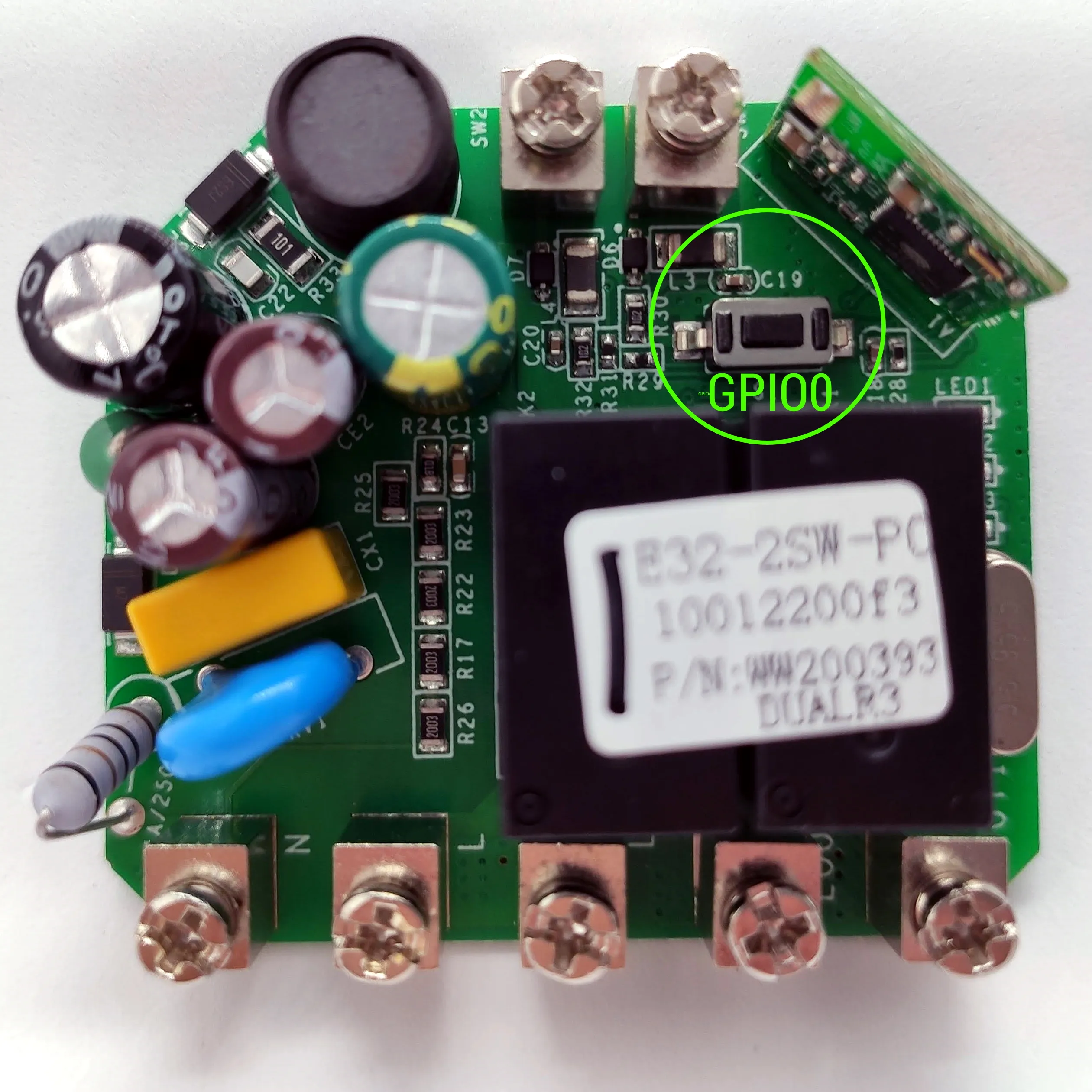
You can identify the v2 from the v1.x by the markings on the PCB and on the energy measurement chip. The photo right below is from Sonoff Dual R3 v2. All Photos on the flashing guide thereafter are from Sonoff Dual R3 v1.6 as there is no difference in the flashing process.
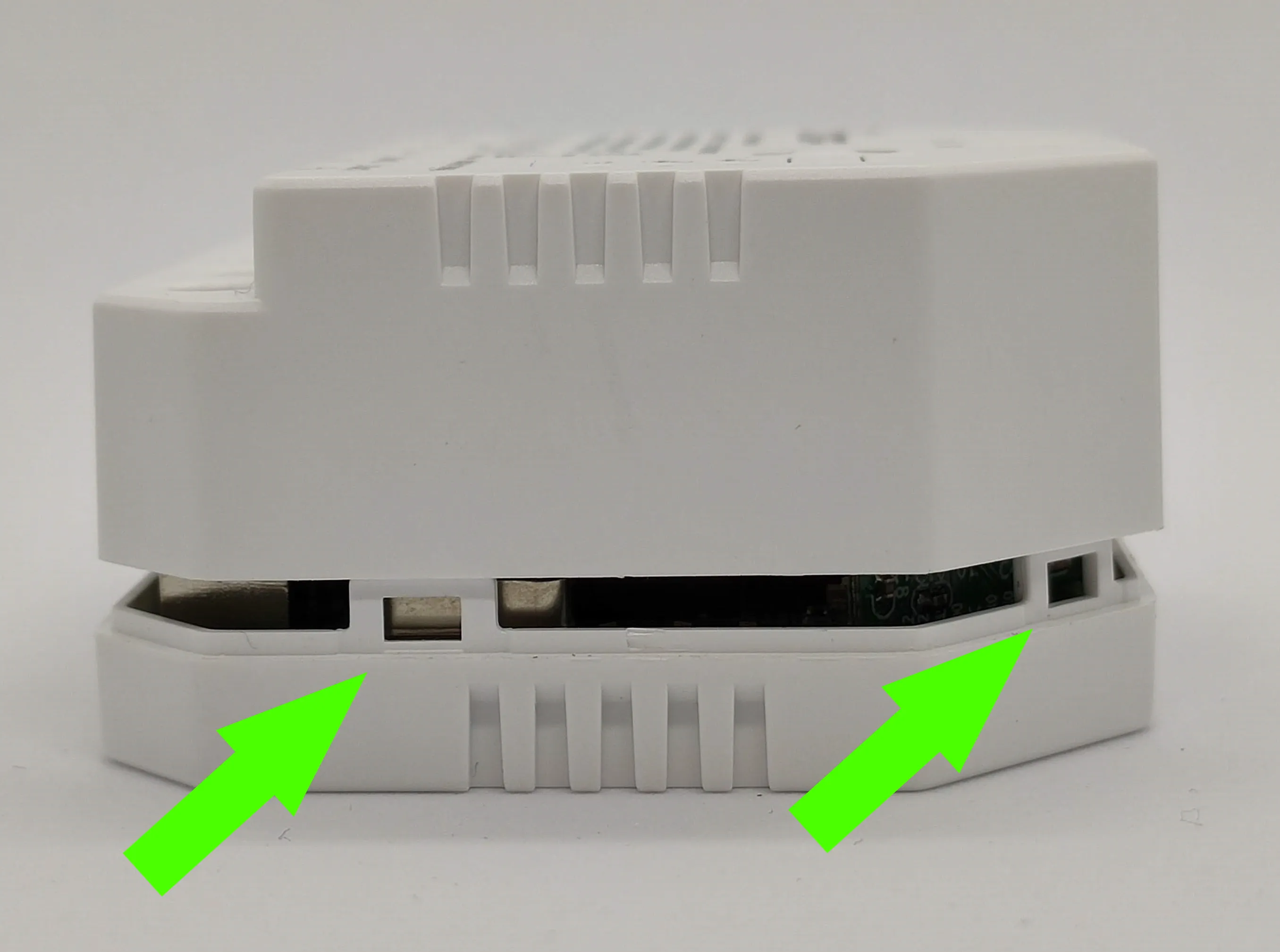
Opening the Case
Press the case to release the clips. My case was not glued at all but some might be. After opening it, the PCB will simply pop out.
Serial Flashing (photos shows Sonoff Dual R3 v1.6)
Disconnect the device from mains power! Like for real!
The four needed pins (3V3, RX, TX and GND) are available at the back of the PCB and can be easily identified.
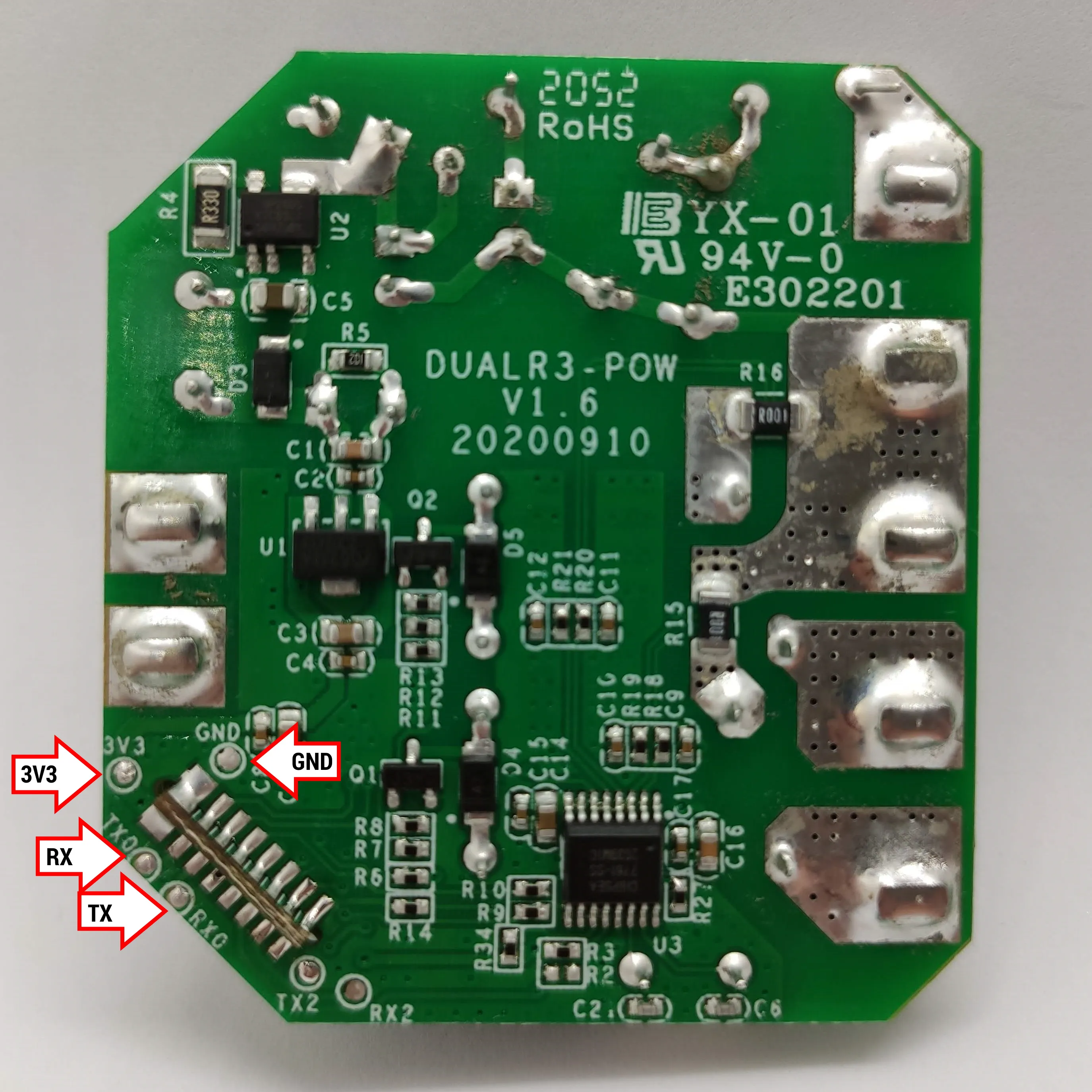
Connect them to the serial-to-USB adapter. If you have alligator clips or some ingenuity you can do it without soldering, notice that ground is connected to any ground pin on the board, not the marked pad necessarily.
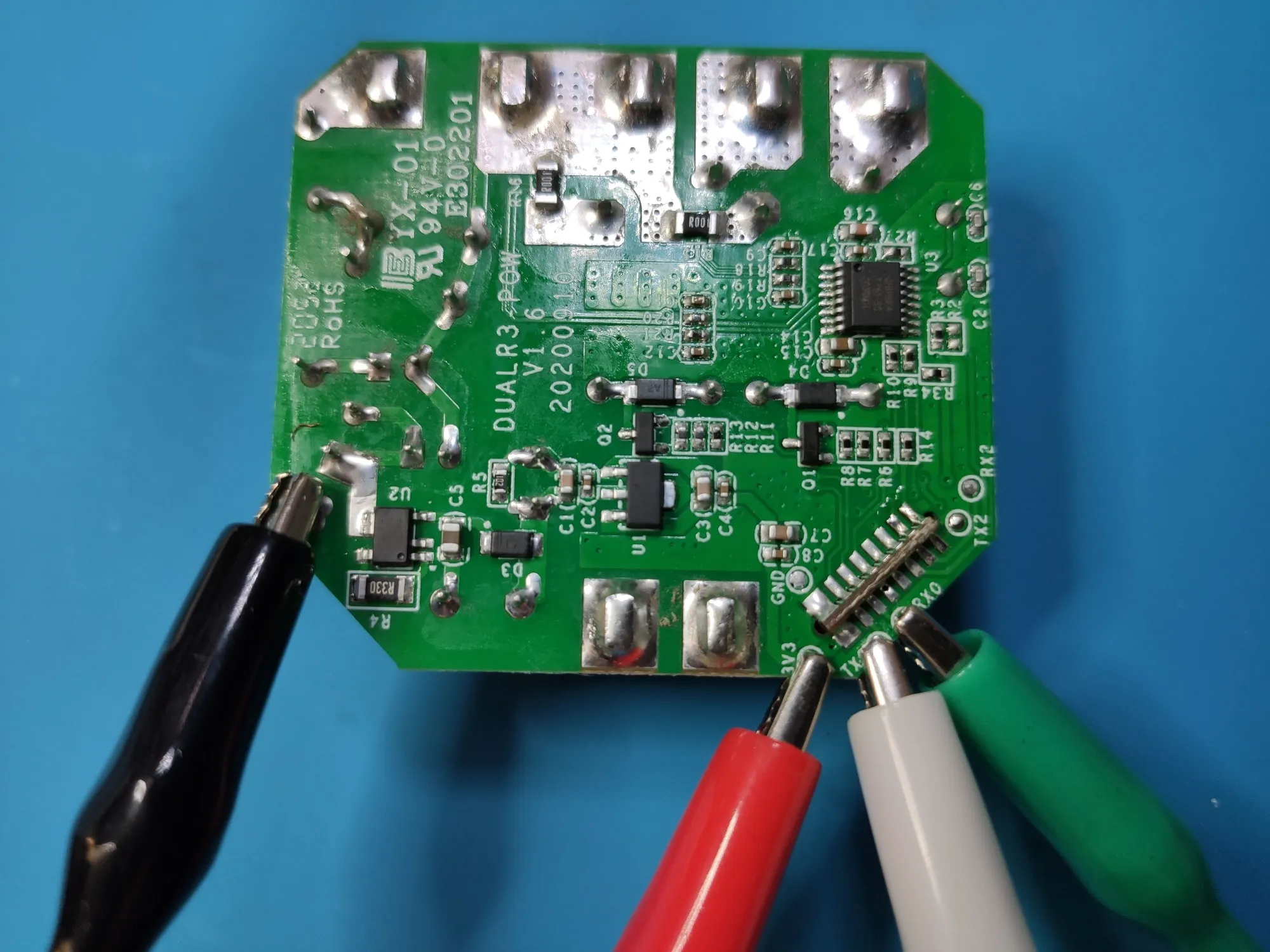
To enter flash mode you need to connect GPIO0 to GND. Luckily Sonoff decided to give you a practical button that does just that.
Tasmota Web Installer
For easiest flash use Tasmota Web Installer.
esptool.py
If you are installing from scratch then use tasmota32.factory.bin which includes the necessary bootloader files.
esptool.py --chip esp32 --port COM5 --baud 921600 --before default_reset --after hard_reset write_flash -z --flash_mode dout --flash_freq 40m --flash_size detect 0x00000 tasmota32.factory.bin
Configuration
After the flash is complete you will have to connect the DUALR3 to mains and configure Tasmota with webUI using the Wi-Fi AP. ESP32 usually cannot boot properly with power supplied by the serial-to-USB adapter!
Apply the template and make sure “Module 0” is selected. If the power readings are off, perform power monitoring calibration.
Zero Cross Detection Support
To enable Zero Cross Detection use this template
{"NAME":"Sonoff Dual R3 (ZCD)","GPIO":[32,0,0,0,7552,0,0,0,0,576,225,0,0,0,0,0,0,0,0,0,0,3200,8128,224,0,0,0,0,160,161,0,0,0,0,0,0],"FLAG":0,"BASE":1}