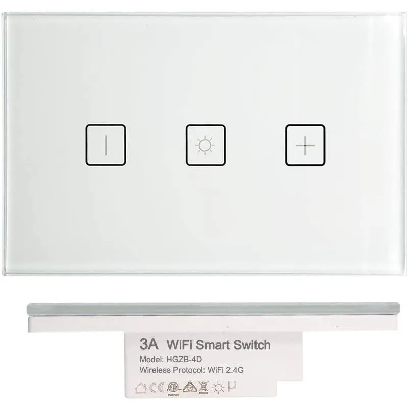
Available from:
Amazon.com.au
Ebay.com.au
Manufacturer:
3asmarthome.com
Install method:
USB to Serial
| GPIO # | Component |
|---|---|
| GPIO00 | User |
| GPIO01 | User |
| GPIO02 | User |
| GPIO03 | User |
| GPIO04 | User |
| GPIO05 | User |
| GPIO09 | None |
| GPIO10 | None |
| GPIO12 | User |
| GPIO13 | User |
| GPIO14 | Led3 |
| GPIO15 | User |
| GPIO16 | User |
| FLAG | None |
{"NAME":"HGZB-4D","GPIO":[255,255,255,255,255,255,0,0,255,255,54,255,255],"FLAG":0,"BASE":54,"CMND":"TuyaMCU 21,2|DimmerRange 11,255"}TuyaMCU 21,2
DimmerRange 11,255
Serial Flashing
If Tuya-Convert isn’t working for you, you can flash it over a serial link as described on Tasmota - Getting Started
To do so you do need to solder on some cables to allow connecting your flashing tool / software of choice.
This Dimmer switch uses a secondary control chip (8s003f3p6) and it communicates with the main control chip (TYWE3S)
using the same connections used for flashing Tasmota. Therefore we have to temporarily disable the secondary control
chip by connecting its NRST line to GND
For more information check out the datasheet for 8s003f3p6
Here is an image of how I’ve done that:

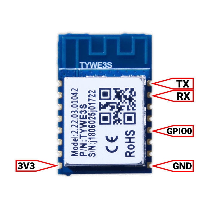
Next step is to connect the serial connection (RX, TX), and GND and 3V3 (VCC) for the serial connection as per image below. Note, you also need to connect GPIO0 to GND to put the TYWE3S chip into programming mode.
After that follow the guide linked above to flash Tasmota.
Credit for the information goes to HoustonAU on the Home Assistant Forum.
Pinout
 .
.


