Available from:
Aliexpress.com
Banggood.com
Install method:
USB to Serial
| GPIO # | Component |
|---|---|
| GPIO00 | None |
| GPIO01 | Serial Tx |
| GPIO02 | None |
| GPIO03 | Serial Rx |
| GPIO04 | Relay1 |
| GPIO05 | None |
| GPIO09 | None |
| GPIO10 | None |
| GPIO12 | None |
| GPIO13 | None |
| GPIO14 | None |
| GPIO15 | None |
| GPIO16 | None |
| FLAG | None |
{"NAME":"D06 Door Sensor","GPIO":[0,148,0,149,21,0,0,0,0,0,0,0,0],"FLAG":0,"BASE":18}This device now comes with a Wi-Fi module incompatible with Tasmota

Warning! Since 2022-02-22 ships with CB3S (BK7231N)
Old hardware instructions
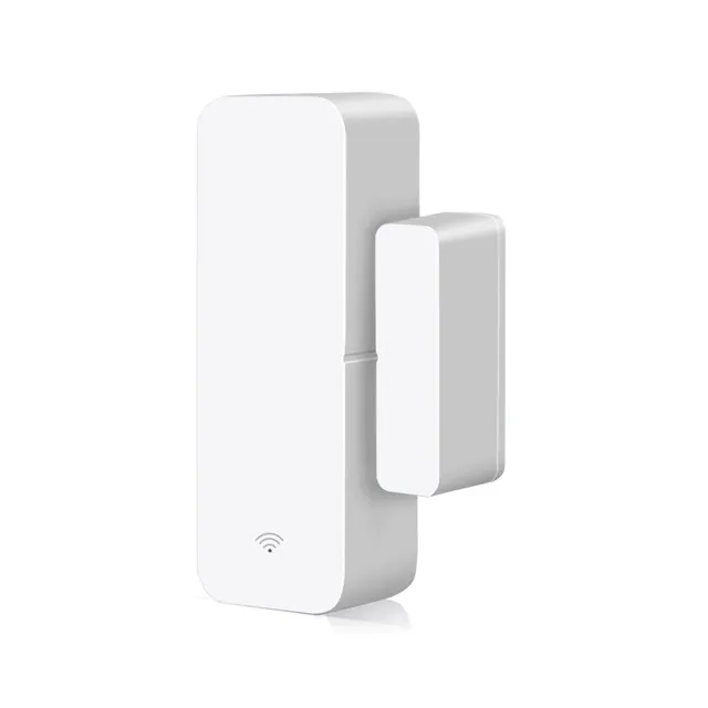
This is a Tuya battery powered contact sensor. Runs on two AAA batteries (not supplied with the device).
This sensor can be found for around 6$ on AliExpress!
Flashing
To have best results with this type of device I strongly recommend compiling a stripped down binary. There’s an unofficial tasmota-battery.bin binary, compiled from current development release. Flash at your own risk.
Serial
Easily disassembled by removing the back plate, then prying away the plastic with the battery holder and pcb.
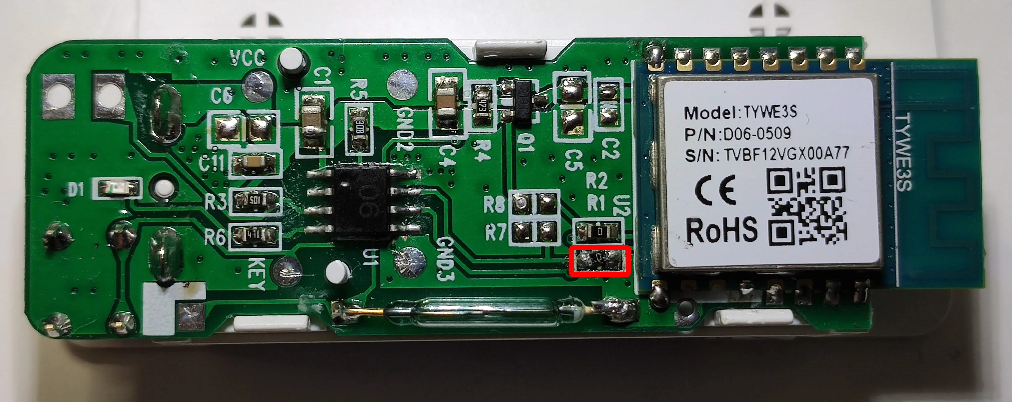
The PCB has no visible serial number or other marking on it but the MCU is marked D06 (edit: its an STC 8051). It powers on the TYWE3S module on probe contact on “Reset” button press for a short amount of time sufficient to send alerts.
To flash the device solder directly to TYWE3S TX, RX, VCC and GND pins (optional: solder GPIO0 to GND but you only need to connect it to GND during boot). You also need to temporarily remove the marked resistor to prevent the MCU from interfering with the flashing process. Resolder it back or bridge the connection once flashing is complete.
There appears to be a new revision of the board, easily identified by the additional test points:
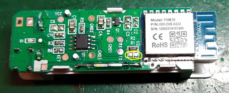
Flashing procedure is the same, but this time there is a track joining the two pads of R1 that will need to be cut (by scratching through the copper layer with a scalpel or similar) - simply removing the 0-ohm resistor is not enough.
Configuration
If you’re using battery power you will have to periodically wake up the sensor with the reset button or by shorting the GND and KEY pads on the PCB.
In this case we will not use the TuyaMCU base but will instead capture raw serial traffic and emulate a Tuya module with a couple of rules executed on system boot.
Disable multipress button options to prevent an accidental device reset, disable Power Cycle recovery, disable bootloop recovery and enable power retain to keep the power state in your broker.
Backlog SetOption1 1; SetOption65 1; SetOption36 0; PowerRetain 1
Add rule
rule1
on system#init do baudrate 9600 endon
on system#boot do backlog serialsend5 55AA000800010008; delay 5; serialsend5 55AA000200010406 endon
Don’t forget to turn on the rule: Rule1 1
rule2
on serialreceived#data=55AA0008000C00020202020202010100010123 do power 1 endon
on serialreceived#data=55AA0008000C00020202020202010100010022 do power 0 endon
on serialreceived#data=55AA0008000C00010101010101030400010223 do publish2 stat/%topic%/BATTERY high endon
on serialreceived#data=55AA0008000C00010101010101030400010122 do publish2 stat/%topic%/BATTERY medium endon
on serialreceived#data=55AA0008000C00010101010101030400010021 do publish2 stat/%topic%/BATTERY low endon
Turn on the rule: Rule2 1
The relay in the template is a dummy relay used to keep power states with rule2.
You can adapt the publish topics and payloads to work with your system, these are formed to work in my environment. Battery messages are sent on every boot but we’re still publishing those messages with the retained flag so the battery state will always be reachable.
Remember that the reset button on the back will trigger the sensor which is useful to test the device periodically and refresh battery status so you don’t run out accidentally.
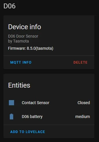
Home Assistant Integration
Since autodiscovery won’t work on this type of device and configuration.yaml is so 2019 we will create a manual autodiscovery message and end up with a Device in HA with two entities. You need Tasmota 8.5+ to do this.
The payload is presented in yaml form for easier editing. To get a valid payload, take the yaml block and convert it to JSON. I recommend using onlineyamltools. If you have changed topics and payloads in the rule you need to change them here too.
Set your device Topic to something meaningful because it will be used as part of the device name in HA.
Contact Sensor
name: %topic% Contact Sensor
state_topic: stat/%topic%/RESULT
value_template: '{{value_json.POWER}}'
payload_off: 'OFF'
payload_on: 'ON'
device_class: opening
unique_id: '%deviceid%_contact'
device:
  identifiers:
    - '%deviceid%'
  name: %topic%
  manufacturer: Tasmota
platform: mqtt
Paste the converted json payload in the rule instead of <json_payload>
rule3 on system#boot do publish2 homeassistant/binary_sensor/%deviceid%_contact/config <json_payload> endon
Battery Sensor
name: '%topic% Battery'
state_topic: stat/%topic%/BATTERY
value_template: '{{ value }}'
icon: 'mdi:battery'
unique_id: '%deviceid%_battery'
device:
  identifiers:
    - '%deviceid%'
  name: %topic%
  manufacturer: Tasmota
Paste the converted json payload in the rule instead of <json_payload>
rule3 + on system#boot do publish2 homeassistant/sensor/%deviceid%_battery/config <json_payload> endon
This will append a new line to the existing rule3.
Don’t forget to enable the rule with Rule3 1
When the sensor boots again it will send the two autodiscovery messages and your device will appear in HA devices list.