


Available from:
Aliexpress.com
Banggood.com
Install method:
USB to Serial
| GPIO # | Component |
|---|---|
| GPIO00 | User |
| GPIO01 | User |
| GPIO02 | Led_i 1 |
| GPIO03 | User |
| GPIO04 | User |
| GPIO05 | Led_i 2 |
| GPIO09 | User |
| GPIO10 | User |
| GPIO12 | Relay 3 |
| GPIO13 | Relay 4 |
| GPIO14 | Relay 2 |
| GPIO15 | User |
| GPIO16 | Relay 1 |
| GPIO17 | User |
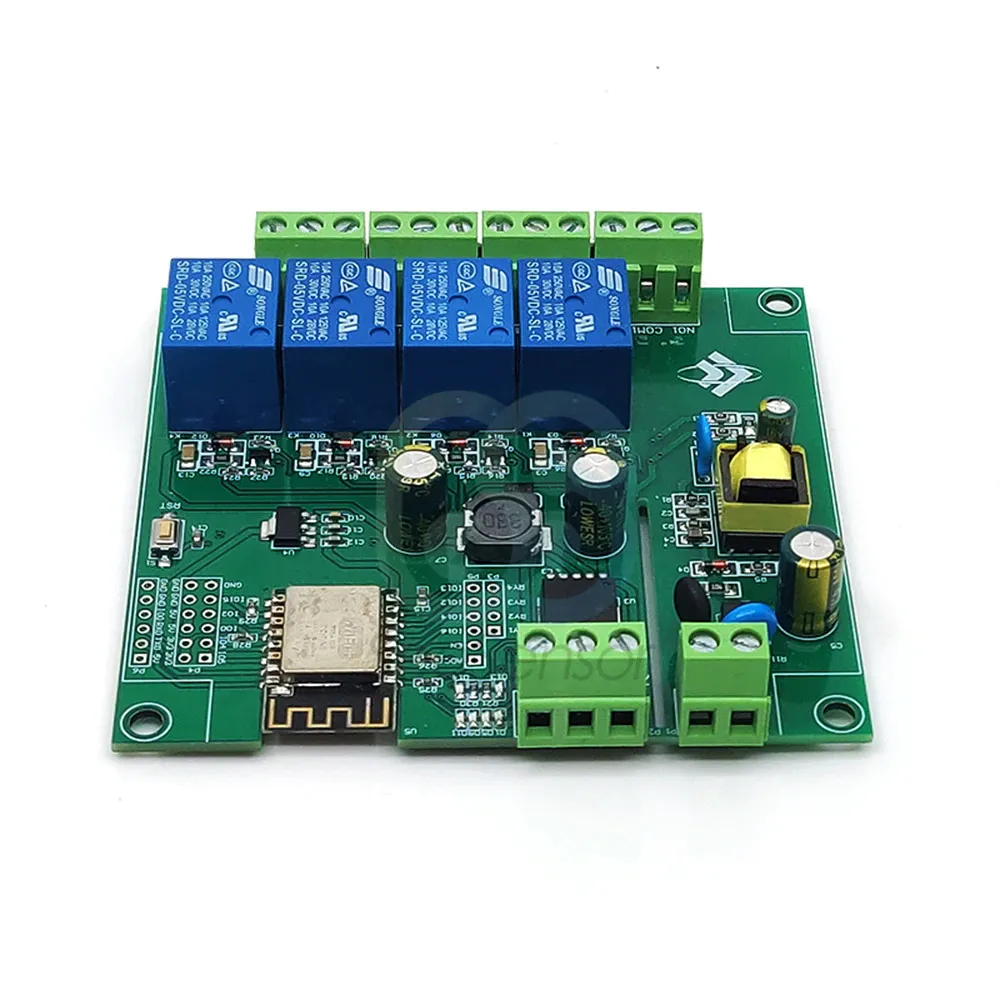
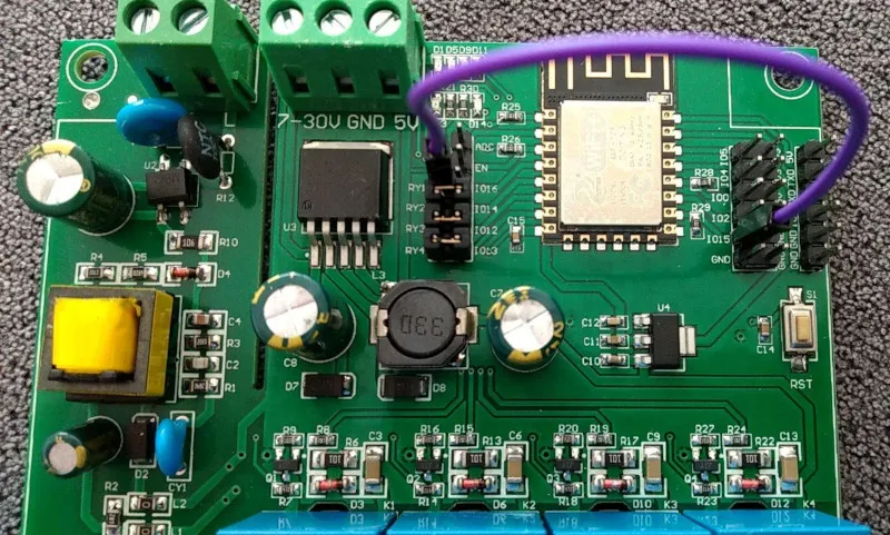
{"NAME":"ESP12F_Relay_X4","GPIO":[1,1,320,1,1,321,1,1,226,227,225,1,224,1],"FLAG":0,"BASE":18}Headers must be soldered and jumpers needs to be installed for enabling relays.
The board uses GPIO16 and so Relay1 is always turned ON when power is applied to the board, causing a brief on/off pulse on the relay as Tasmota loads and turns it off again. Of course, if the last state was ON, then it will stay ON. It’s still a very useful board at a bargain price; just a shame the designer was too lazy to route a different GPIO pin. (Although rather than using the provided link pair, you could link to IO0 IO2 or IO15 thru-holes on the side of the board instead of IO16, and change the template to suite.)
Example for when Relay1 is connected to GPIO15:
Suitable template:
{"NAME":"ESP12F_Relay_X4","GPIO":[1,1,1,1,1,320,1,1,226,227,225,224,1,1],"FLAG":0,"BASE":18}