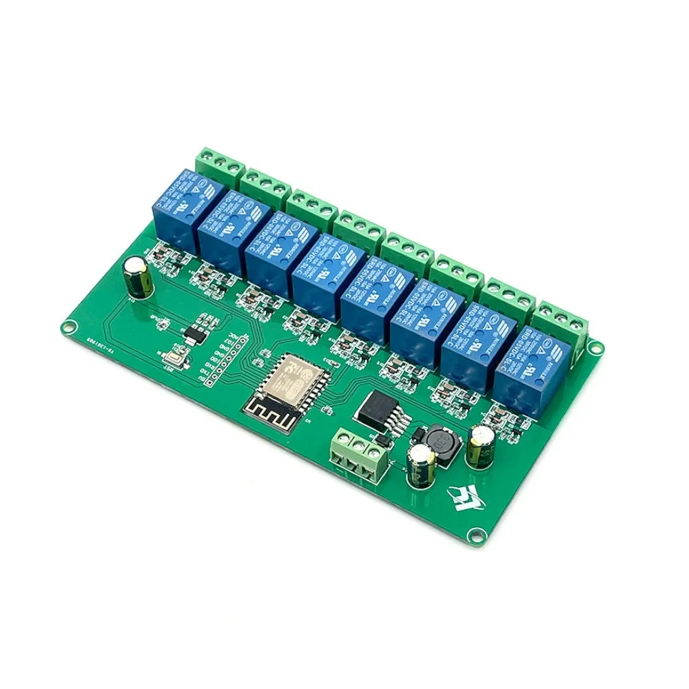
Available from:
Banggood.com
Aliexpress.com
Install method:
USB to Serial
| GPIO # | Component |
|---|---|
| GPIO00 | Relay 6 |
| GPIO01 | User |
| GPIO02 | User |
| GPIO03 | User |
| GPIO04 | Relay 7 |
| GPIO05 | Relay 8 |
| GPIO09 | None |
| GPIO10 | None |
| GPIO12 | Relay 3 |
| GPIO13 | Relay 4 |
| GPIO14 | Relay 2 |
| GPIO15 | Relay 5 |
| GPIO16 | Relay 1 |
| GPIO17 | User |
{"NAME":"ESP12F_Relay_X8","GPIO":[229,1,1,1,230,231,0,0,226,227,225,228,224,1],"FLAG":0,"BASE":18}Headers can be soldered.
The board uses GPIO16 and so Relay1 is always turned ON when power is applied to the board, causing a brief on/off pulse on the relay as Tasmota loads and turns it off again. Of course, if the last state was ON, then it will stay ON. It’s still a very useful board at a bargain price.
On the board are available RX, TX, GPIO0 pins for programming and GPIO2 and GPIO17 (ADC), but GPIO0 is used for relay 6, GPIO2 is always pulled up (necessary at boot) and GPIO17 has a limited range of 0-1V.
The board can be powered with 5Vdc or with 7-29Vdc, but remember that GPIO pins are not 5V tolerant.
Note the board will NOT flash with 3.3v - it must have 5v connected to the header socket labelled 5v on the pin headers or through the screw down connector


