Available from:
Aliexpress.com
Store.gl-inet.com
Alibaba.com
Manufacturer:
Gl-inet.com
Install method:
USB to Serial
| GPIO # | Component |
|---|---|
| GPIO00 | Button 1 |
| GPIO01 | None |
| GPIO02 | None |
| GPIO03 | None |
| GPIO04 | None |
| GPIO05 | None |
| GPIO09 | None |
| GPIO10 | None |
| GPIO12 | Led_i 2 |
| GPIO13 | I2C SCL 1 |
| GPIO14 | Led 1 |
| GPIO15 | I2C SDA 1 |
| GPIO16 | None |
| GPIO17 | None |
| GPIO18 | ETH MDIO |
| GPIO19 | None |
| GPIO20 | None |
| GPIO21 | None |
| GPIO22 | None |
| GPIO23 | ETH MDC |
| GPIO24 | None |
| GPIO25 | None |
| GPIO26 | None |
| GPIO27 | None |
| GPIO6 | None |
| GPIO7 | None |
| GPIO8 | None |
| GPIO11 | None |
| GPIO32 | LedLink |
| GPIO33 | Button 2 |
| GPIO34 | None |
| GPIO35 | None |
| GPIO36 | None |
| GPIO37 | None |
| GPIO38 | None |
| GPIO39 | None |
{"NAME":"GL-S10 v1.0","GPIO":[32,0,0,0,0,0,0,0,321,608,288,640,0,0,5600,0,0,0,0,5568,0,0,0,0,0,0,0,0,544,33,0,0,0,0,0,0],"FLAG":0,"BASE":1,"CMND":"EthType 0 | EthAddress 1 | EthClockMode 3"}WARNING!
New versions marked V2.1 come with an unsupported Ethernet chip IP101GRI and cannot use this configuration
Flashing
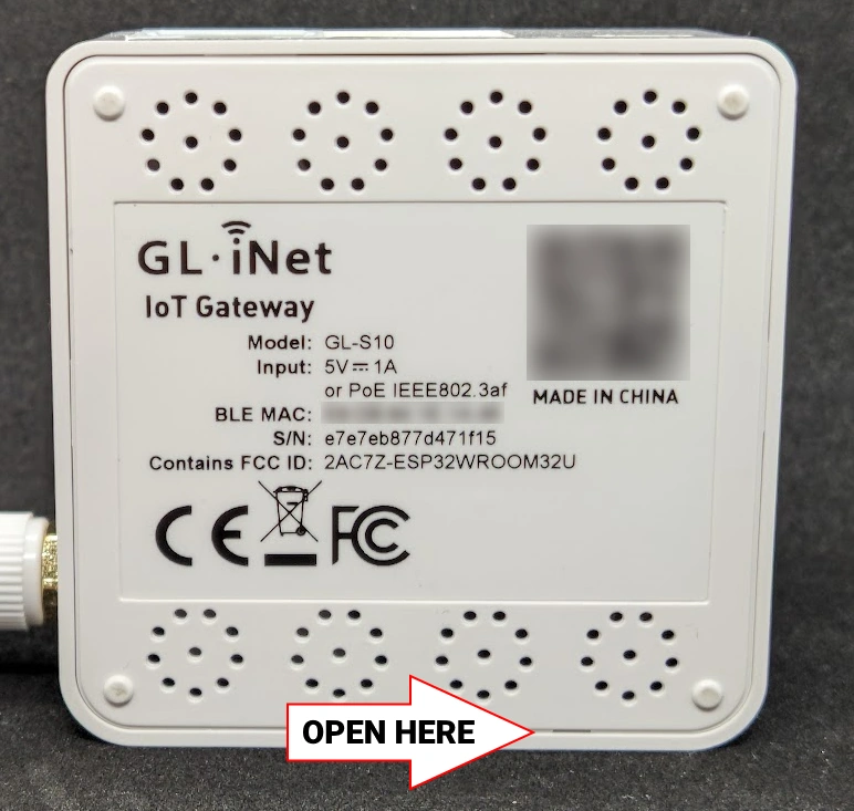
USB port is for power only, to flash you will need to open the device.
This is done simply by prying away the bottom starting at the notch marked in the below image.
Flash using the labelled pins. I recommend connection only TX, RX and GND while powering the device via the USB port.
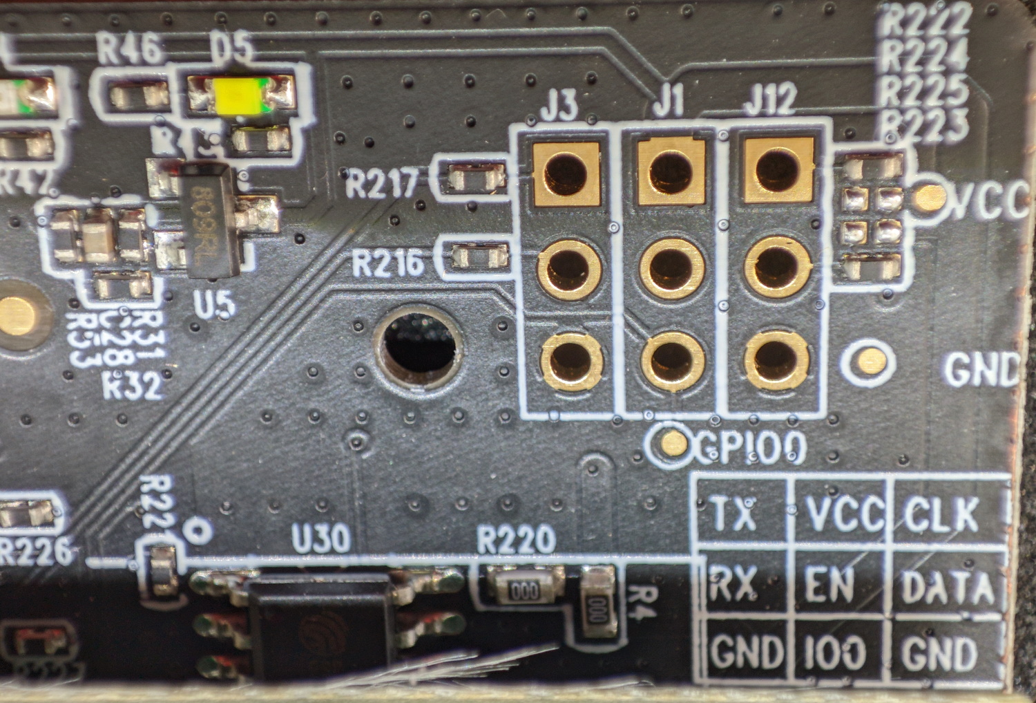
To put it in flash mode use the button next to the USB port or the labelled IO0 header.
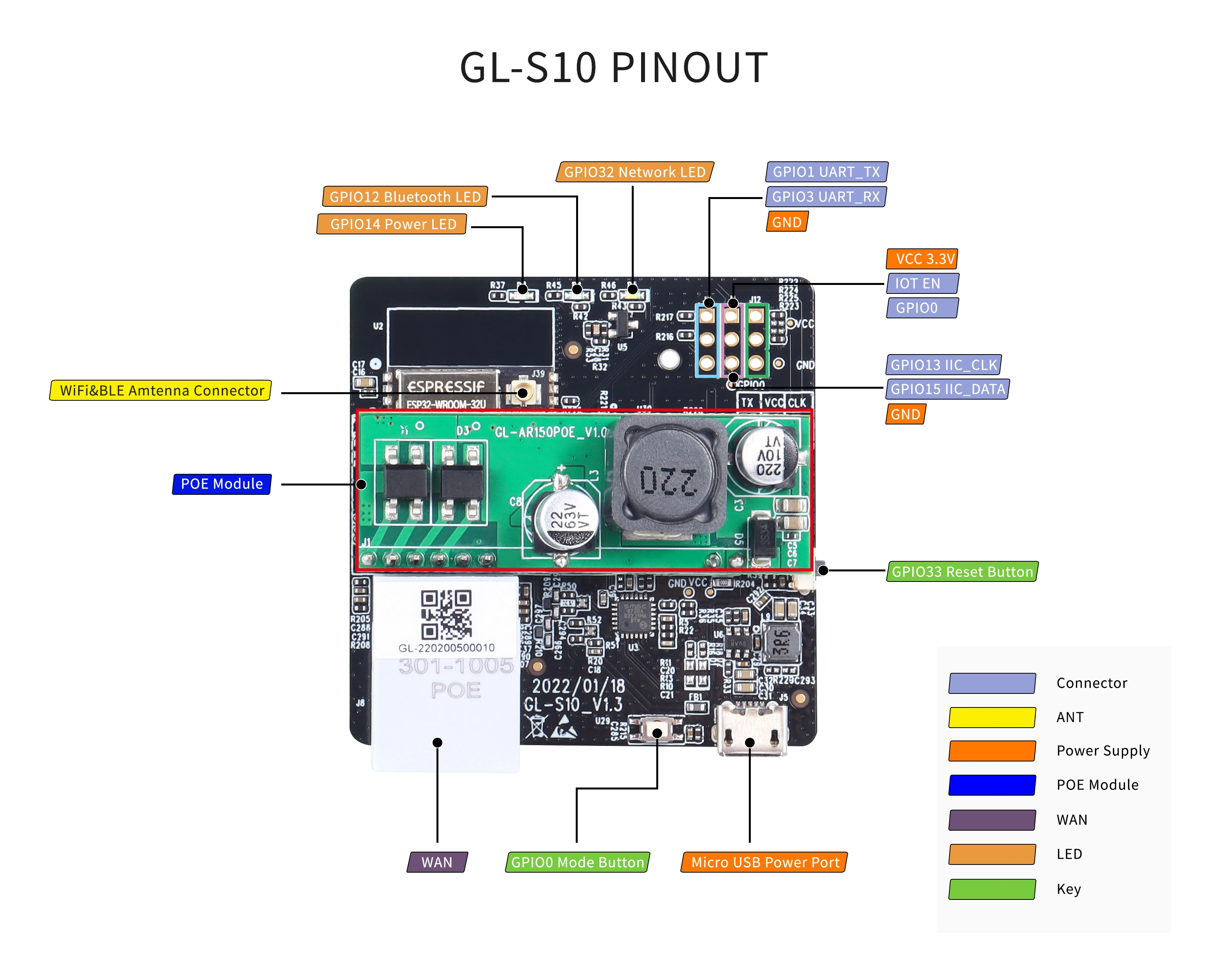
Configuration
I2C port is assigned to GPIO13 and GPIO15, Reset button is Button1 and Boot button is Button2. Each test pad on the PCB is assigned as User.