


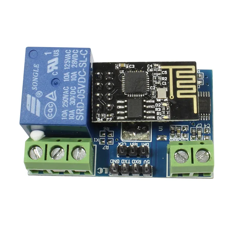
LC Technology ESP8266 5V Relay Board (ESP8266-01S)
Available from:
Amazon.de
Manufacturer:
Chinalctech.com
Install method:
USB to Serial
| GPIO # | Component |
|---|---|
| GPIO00 | Relay1 |
| GPIO01 | Serial Tx |
| GPIO02 | None |
| GPIO03 | Serial Rx |
| GPIO04 | None |
| GPIO05 | None |
| GPIO09 | None |
| GPIO10 | None |
| GPIO12 | None |
| GPIO13 | None |
| GPIO14 | None |
| GPIO15 | None |
| GPIO16 | None |
| FLAG | Analog |
Configuration (old format, will be converted to new template when applied)
{"NAME":"ESP8266-01S","GPIO":[21,148,0,149,0,0,0,0,0,0,0,0,0],"FLAG":1,"BASE":18}The LC Technology relay devices use GPIO1 and GPIO3 for the serial communications used to control the relays. You do not need to specify these in the template. SerialSend uses these standard serial communications GPIO by default.
- Set module to Generic (18) (in module configuration and click save)
- Set D3 GPIO0 as Relay1 (21) (in module configuration and click save)
- Disable SerialLog (type seriallog 0 in the Tasmota console)
- If you use LC Technology v1.2 or v3 (China version) and this rule does not work, try to use 115200 baudrate (in combination with only D3 GPIO0 as Relay1 configured).
- Add the following rules typing in the console:
Rule1
 on System#Boot do Backlog Baudrate 9600; SerialSend5 0 endon
 on Power1#State=1 do SerialSend5 A00101A2 endon
 on Power1#State=0 do SerialSend5 A00100A1 endon
Enable the rule: Rule1 1
If that doesn’t work for you, you may find that using Power1#Boot as the event to trigger the baud rate setting (instead of System#Boot) works, as it did for me. So the alternate rule is:
Rule1
on Power1#Boot do Backlog Baudrate 9600; SerialSend5 0 endon
on Power1#State=1 do SerialSend5 A00101A2 endon
on Power1#State=0 do SerialSend5 A00100A1 endon