


Available from:
Torelectric.ro
Manufacturer:
Alibaba.com
Install method:
USB to Serial
| GPIO # | Component |
|---|---|
| GPIO00 | None |
| GPIO01 | None |
| GPIO02 | Button1 |
| GPIO03 | None |
| GPIO04 | LedLink |
| GPIO05 | PWM2 |
| GPIO09 | None |
| GPIO10 | None |
| GPIO12 | PWM3 |
| GPIO13 | None |
| GPIO14 | Led2 |
| GPIO15 | PWM1 |
| GPIO16 | None |
| FLAG | None |
{"NAME":"QS-WIFI-RGBCW","GPIO":[0,0,17,0,157,38,0,0,39,0,53,37,0],"FLAG":0,"BASE":18}This device contains an ESP8266-LM1 chip inside.
Manual :
- https://fccid.io/2AJK8-LM1/User-Manual/User-Manual-3857005.pdf
- https://usermanual.wiki/Lingan-Intelligent-Technology/LM1
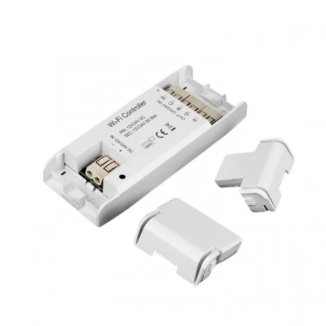
Pinout :

In order to flash you need to solder on temporarily some wires to the following pins :
GND- top right pin3v3- top left pinUTXD- bottom, 2nd pin from the right - will connect to TXD on the FTDI boardURXD- bottom, 3rd pin from the left - will connect to RXD on the FTDI boardIO0- left side 3rd pin from the top - used to reset the device
Note, there is a Reset button on the device but it cannot be used to enter flashing mode, you’ll need to connect the 5th cable IO0 to GND when connecting the FTDI cable.
Note there is no led on the board so you won’t see the status, you might be able to use a led strip, in my case it was quite flacky to show the status (sometimes the red color turned on when it was in flashing mode, otherwise none of the colors turned on but the flashing worked correctly)
Note: didn’t try with Tuya-Convert, might work with that too.
GPIO Assignments
GPIO2- Reset button, if you configure it asButton1then you can use it to turn On/Off the light stripGPIO4- Warm white connectorGPIO5- Green connectorGPIO12- Blue connectorGPIO14- Cool white connectorGPIO15- Red connector After flashing you can use one of the following templates, depending on what kind of led strip you use.
Configurations
RGB Strip
{"NAME":"QS-WIFI-RGB","GPIO":[0,0,17,0,0,38,0,0,39,0,0,37,0],"FLAG":0,"BASE":18}
RGBW Strip
{"NAME":"QS-WIFI-RGBW","GPIO":[0,0,17,0,40,38,0,0,39,0,0,37,0],"FLAG":0,"BASE":18}
Up to 5 individual light strips
{"NAME":"QS-WIFI-5STRIP","GPIO":[0,0,17,0,40,38,0,0,39,0,41,37,0],"FLAG":0,"BASE":18}
You will also need to run the following command in order to get individual sliders for each led strip
SetOption68 1
Of course, you can play with the templates and configure it the way you want.