Available from:
Aliexpress.com
Amazon.de
Kruidvat.nl
Install method:
USB to Serial
| GPIO # | Component |
|---|---|
| GPIO00 | None |
| GPIO01 | Tuya Tx |
| GPIO02 | None |
| GPIO03 | Tuya Rx |
| GPIO04 | None |
| GPIO05 | None |
| GPIO09 | None |
| GPIO10 | None |
| GPIO12 | None |
| GPIO13 | None |
| GPIO14 | None |
| GPIO15 | None |
| GPIO16 | None |
| FLAG | None |
{"NAME":"TYMC-1","GPIO":[0,107,0,108,0,0,0,0,0,0,0,0,0],"FLAG":0,"BASE":54}Unsupported Hardware
Sadly, new versions of this sensor come with an unsupported XR4 module
Old Hardware Version Instructions
Found listed also as MC400A under various brand names.
Please read TuyaMCU article to understand the terminology and configuration process.
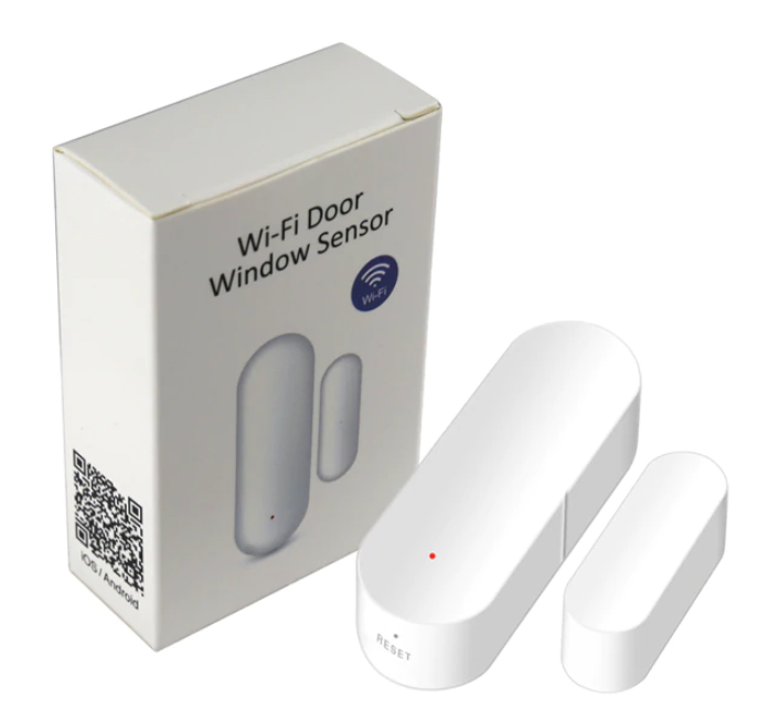
This is a Tuya/Smart Life battery powered contact (door or window) sensor. Runs on two AAA batteries (not supplied with the device).
Identified with MCU Product ID: {"p":"hx5ztlztij4yxxvg","v":"1.0.0"} which is also printed on the TYWE3S module.


Flashing
To have best results with this type of device I strongly recommend compiling a stripped down binary. There’s an unofficial binary, compiled from current development release. Flash at your own risk.
Example user_config_override defines (for Tasmota 8.2+).
Serial
Easily disassembled by removing the back plate, unscrewing the screw in the battery holder and prying away the plastic using the bottom slot.

The PCB has only the 20191022 marking on it and a prominent TYWE3S module with the product ID printed. There are broken out pins for 3v3, RX, TX and GND but to be able to solder a pin header in them you need to desolder the battery holder which is probably not worth the trouble since all the pins are accessible on the TYWE3S.

MCU details
STC8F1K08S2 MCU, situated on the left of the broken out pins, powers on the Tuya module on reed actuation or on “Reset” bottom button press for a short amount of time sufficient to send opening or closing message.


| MCU PIN | Connection | explanation |
|---|---|---|
| P5.4 | D2 | LED |
| P5.5 | SC9JF | controls ESP power via EN pin on voltage regulator |
| P3.3 | R12 | RESET button |
| P3.2 | S1 | reed switch |
| P3.1 | RX | ESP and broken out pin |
| P3.0 | TX | ESP and broken out pin |
Due to this design it is somewhat difficult to tuya-convert or even configure the device compared to non-battery powered ones. I flashed the device over serial powering the TYWE3S from the USB-to-serial adapter.
Configuration
If you’re using battery power you need to prevent the device from going to sleep by actuating the reed switch constantly (approximately every 5 seconds) during the configuration or use the serial message.
You can use
SerialSend5 55AA000200010002
shortly after boot to put the device into wi-fi search mode (rapidly blinking red LED) which will keep it powered on for around 60 seconds.
Change device to a TuyaMCU module (or apply the provided template, result is the same)
Module 54
Disable multipress button options to prevent a device reset or Wi-Fi AP config mode, disable Power Cycle recovery, turn on TuyaReceived publish to MQTT and set switchmode to follow instead of toggle
Backlog SetOption1 1; SetOption65 1; SetOption66 1; SwitchMode 1
Switch the device to battery powered sensor mode (fnId 51):
TuyaMCU 51,21
Check with TuyaMCU for the following configuration:
{"TuyaMCU":[{"fnId":11,"dpId":1},{"fnId":51,"dpId":21}]}
Functions
dpID 1 reed switch: closed = off / open = on
dpID 3 battery power: 0 = low / 1 = medium / 2 = high
The button labelled reset can wake up the device with a short press or put it into Wi-Fi config mode on long press.
dpID 1 is assigned to Relay1 by default.
There is no function in Tasmota for enum dpID’s currently so we will use a rule to report battery status (high, medium or low) to a custom topic (change it to any other topic suitable for you)
Rule1 ON TuyaReceived#Data=55AA00050005030400010213 DO publish2 stat/%topic%/BATT high ENDON ON TuyaReceived#Data=55AA00050005030400010112 DO publish2 stat/%topic%/BATT medium ENDON ON TuyaReceived#Data=55AA00050005030400010011 DO publish2 stat/%topic%/BATT low ENDON
UPDATED: Actual State on/off
Rule2 ON TuyaReceived#Data=55AA0005000501010001000C DO power 0 ENDON ON TuyaReceived#Data=55AA0005000501010001010D DO power 1 ENDON
Don’t forget to turn on the rule: Rule1 1 and ‘Rule2 1’
And there it is, relatively small battery and Tasmota powered contact sensor.
Final Notes
There is a significant delay (~4s on my network with the latest stripped down binary and a static IP) between reed actuation and first MQTT message so I don’t recommmend this in critical spots where a fast response is required.
If the batteries are too weak, sensor might be stuck in a bootloop or spawn an ESP-XXXXX AP. The bootloop can reset Tasmota to “factory defaults”. You can disable bootloop protection with SetOption36 0 but that might also put the sensor in a permanent bootloop until the battery dies.


