


Available from:
Aliexpress.com
Banggood.com
Install method:
USB to Serial
| GPIO # | Component |
|---|---|
| GPIO00 | None |
| GPIO01 | Serial Tx |
| GPIO02 | None |
| GPIO03 | Serial Rx |
| GPIO04 | None |
| GPIO05 | None |
| GPIO09 | None |
| GPIO10 | None |
| GPIO12 | None |
| GPIO13 | None |
| GPIO14 | None |
| GPIO15 | None |
| GPIO16 | None |
| FLAG | None |
{"NAME":"W06 Water Sensor","GPIO":[0,148,0,149,0,0,0,0,0,0,0,0,0],"FLAG":0,"BASE":18}This device now comes with a Wi-Fi module incompatible with Tasmota

Warning! Since 2022-03-18 ships with XR809
Old hardware instructions
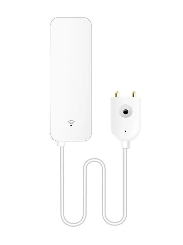
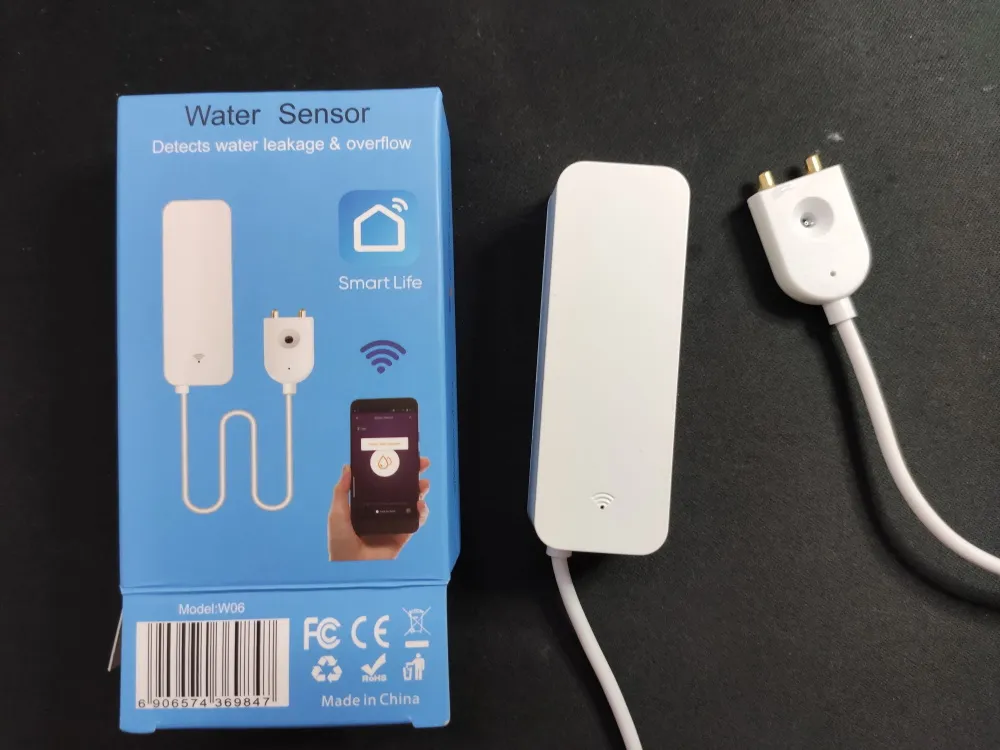
This is a Tuya battery powered water sensor. Runs on two AAA batteries (not supplied with the device).
This sensor can be found for around 6$ on AliExpress!
Identified with MCU Product ID: {"p":"yaxprtktsfxnndyw","v":"1.0.0"}.
Flashing
To have best results with this type of device I strongly recommend compiling a stripped down binary. There’s an unofficial tasmota-battery.bin binary, compiled from current development release. Flash at your own risk.
Serial
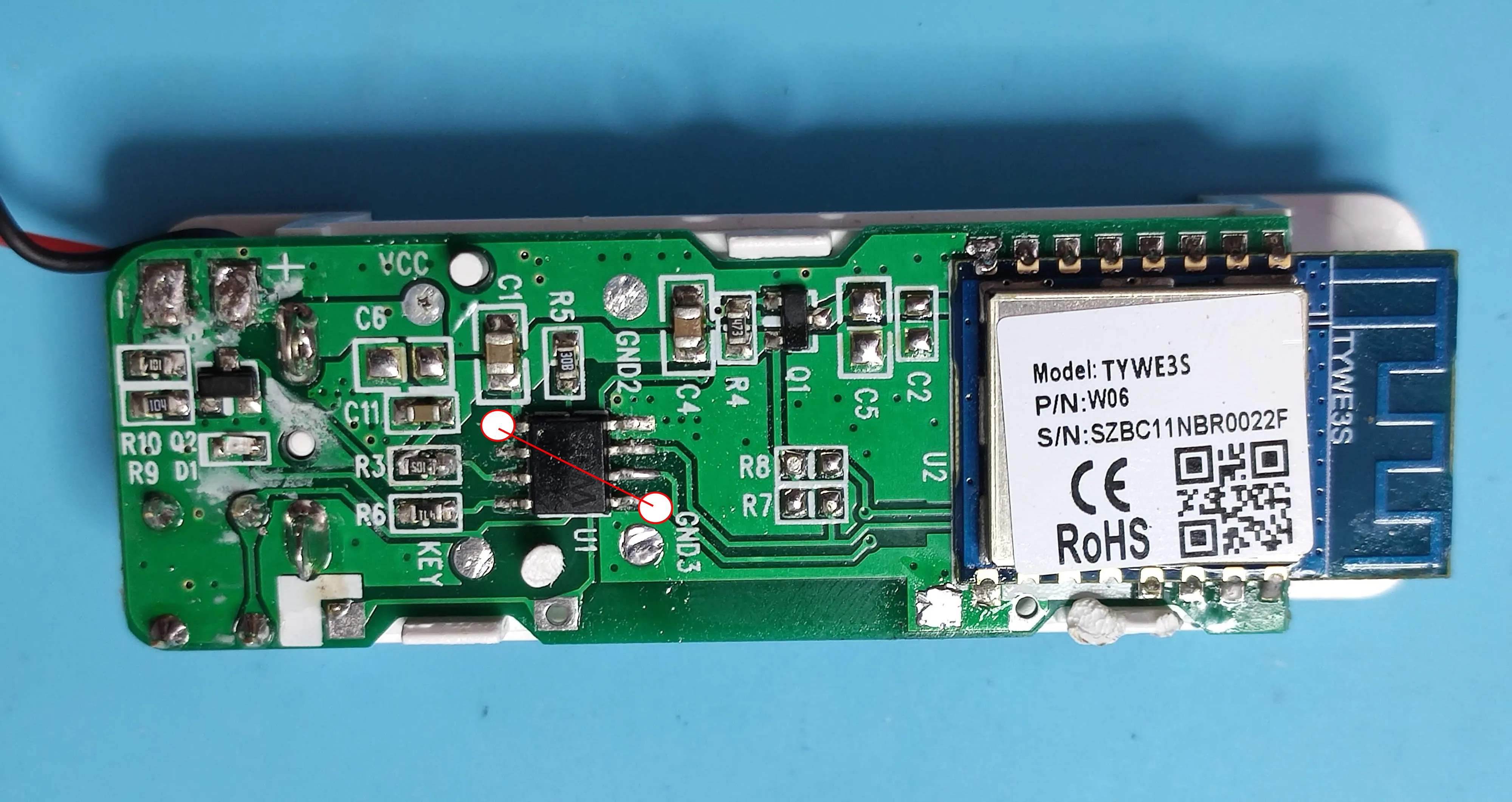
Easily disassembled by removing the back plate, then prying away the plastic with the battery holder and pcb.
The PCB has no visible serial number or other marking on it but the MCU is marked W06 (edit: its an STC 8051). It powers on the TYWE3S module on probe contact on “Reset” button press for a short amount of time sufficient to send alerts.
Due to this design it is difficult to tuya-convert or even configure the device compared to non-battery powered ones. To flash the device solder directly to TYWE3S TX, RX, VCC and GND pins (optional: solder GPIO0 to GND but you only need to connect it to GND during boot). You also need to disable the MCU by connecting the two marked pins and keep them connected during the flashing process, otherwise you will be unable to flash due to MCU interference
Configuration
If you’re using battery power you will have to periodically wake up the sensor with the reset button or by shorting the GND and KEY pads on the PCB.
In this case we will not use the TuyaMCU base but will instead capture raw serial traffic and emulate a Tuya module with a couple of rules executed on system boot.
Disable multipress button options to prevent an accidental device reset, disable Power Cycle recovery and disable bootloop recovery
Backlog SetOption1 1; SetOption65 1; SetOption36 0
Add rule
rule1
on system#init do baudrate 9600 endon
on system#boot do backlog serialsend5 55AA000800010008; delay 5; serialsend5 55AA000200010406 endon
Don’t forget to turn on the rule: Rule1 1
rule2
on serialreceived#data=55AA0008000C00020202020202010400010126 do publish stat/%topic%/LEAK off endon
on serialreceived#data=55AA0008000C00020202020202010400010025 do publish stat/%topic%/LEAK on endon
on serialreceived#data=55AA0008000C00010101010101030400010223 do publish2 stat/%topic%/BATTERY high endon
on serialreceived#data=55AA0008000C00010101010101030400010122 do publish2 stat/%topic%/BATTERY medium endon
on serialreceived#data=55AA0008000C00010101010101030400010021 do publish2 stat/%topic%/BATTERY low endon
Turn on the rule: Rule2 1
You can adapt the publish topics and payloads to work with your system, these are formed to work in my environment. Battery messages are sent on every boot but we’re still publishing those messages with retained flag so the battery state will always be reachable.
Remember that the reset button on the back will trigger the water leak warning which is useful to test the device periodically and refresh battery status so you don’t run out accidentally.