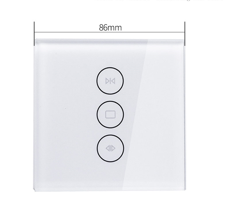
Available from:
Amazon.de
Aliexpress.com
Install method:
USB to Serial
| GPIO # | Component |
|---|---|
| GPIO00 | LedLink |
| GPIO01 | Relay 4 |
| GPIO02 | Led 2 |
| GPIO03 | Button 3 |
| GPIO04 | Relay 3 |
| GPIO05 | Button 2 |
| GPIO09 | None |
| GPIO10 | None |
| GPIO12 | Button 1 |
| GPIO13 | Relay 1 |
| GPIO14 | Led 3 |
| GPIO15 | Relay 2 |
| GPIO16 | Led 1 |
| GPIO17 | None |
{"NAME":"ShutterSwitch","GPIO":[544,227,289,34,226,33,0,0,32,224,290,225,288,0],"FLAG":0,"BASE":18,"CMND":"Rule1 1"}
Added a rule to get it working properly:
Rule1
	on Power1#State=0 do LEDPower1 0 endon
	on Power1#State=1 do LEDPower1 1 endon
	on Power2#State=0 do LEDPower2 0 endon
	on Power2#State=1 do LEDPower2 1 endon
This combines to:
Rule1 on Power1#State=0 do LEDPower1 0 endon on Power1#State=1 do LEDPower1 1 endon on Power2#State=0 do LEDPower2 0 endon on Power2#State=1 do LEDPower2 1 endon
Added some commands too:
InterLock 1,2,3 # lock the relays, only one relay can be on
InterLock    on # switch interlocking on
PowerOnState  0 # keep relay(s) OFF after power up
PowerRetain   0 # don't retain states
SetOption1    1 # restrict button-multipress to single, double and hold actions
LedPower 0	# disables power LED
SetOption31 1	# optional, prevents LED from flashing if WiFi or MQTT are disconnected
SetOption80 1	# enable ShutterMode
Pulsetime3 1 	# this button is used to stop the relays. It can be turned off immediatly
This rule will allow you to toggle the LEDs by long-pressing the middle button:
Backlog Rule2 ON button3#state=3 DO power4 2 ENDON; Rule2 1
Now you must configure the durations : doc here
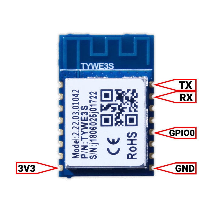
This module is based on the Tuya TYWE3S and TuyaConvert isn’t working anymore (but one can always try..)

The inside of this module looks like this:


And the processor boards:


The device has a separate MCU on board which connects to the TYWE3s module via Rx and Tx.

To be able to flash the device one needs to make 5 connections and CUT the RxD0 line
Important: Cutting the Line in my model resulted in the middle button not working afterwards,
so after the flash I had to resolder the cut connection:

Flashing can be done in several ways: Arduino IDE, VSCode, Platformio, ESP8266Flasher, etc.
!!! BE CAREFUL: always use 3,3 volts for power, NOT 5 volts, and DISCONNECT THE MAINS COMPLETELY while working on the device !!!
The WF-WS01/02/03 have the same boards inside and can be flashed the same way.
Alternate flash method
Unsolder the chip using a heat gun and use this CP210X based board to flash using NodeMCU PyFlasher. Heat the chip sides and push it upwards gently from underneath using tweezers on the label. Had a single problem using this method, one GPIO did not resolder correctly and one LED stayed red. Heated again and applied some solder.
!!! BE CAREFUL: do not tear the contact pads from the board. It will be really hard to make the board work again afterwards.
Pinout
 .
.


