


Available from:
Aliexpress.com
Aliexpress.com
Install method:
USB to Serial
| GPIO # | Component |
|---|---|
| GPIO00 | User |
| GPIO01 | Tuya Tx |
| GPIO02 | User |
| GPIO03 | Tuya Rx |
| GPIO04 | User |
| GPIO05 | User |
| GPIO09 | None |
| GPIO10 | None |
| GPIO12 | User |
| GPIO13 | User |
| GPIO14 | User |
| GPIO15 | User |
| GPIO16 | User |
| FLAG | None |
{"NAME":"YG400A","GPIO":[255,107,255,108,255,255,0,0,255,255,255,255,255],"FLAG":0,"BASE":54}
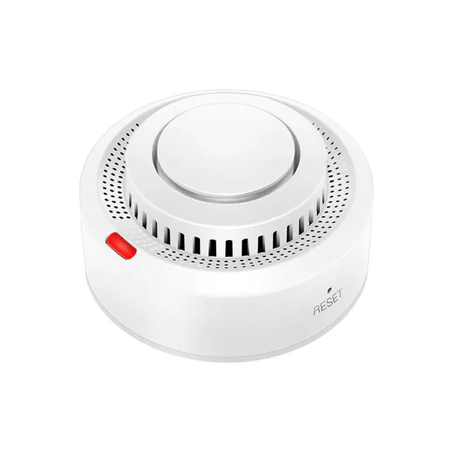
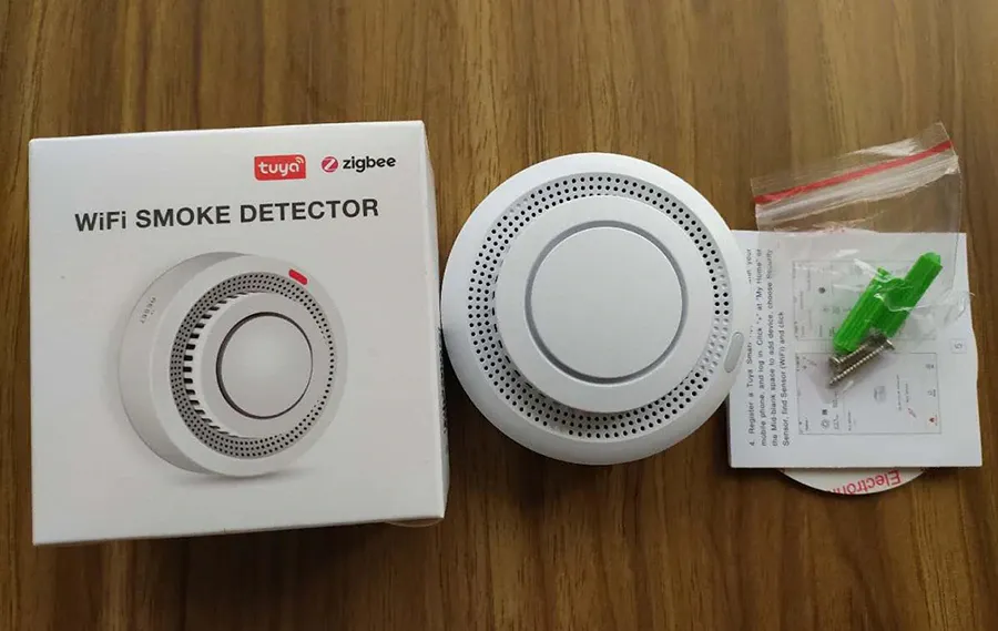
This is a Tuya photoelectric smoke sensor with a alarm. It has a TYWE3S module, a N76E003AQ20 Nuvoton 1T 8051-based Microcontroller and BL5980 Low Voltage Photoelectric Smoke Detector ASIC with Interconnect and Timer Mode. PCB is marked with YG400A hence the model number but it can be found under various brands such as Earykong, Avatto or whitelabel.
Identified with MCU Product ID: {"p":"4w4a6noxfgk0yktc","v":"1.0.0"}.
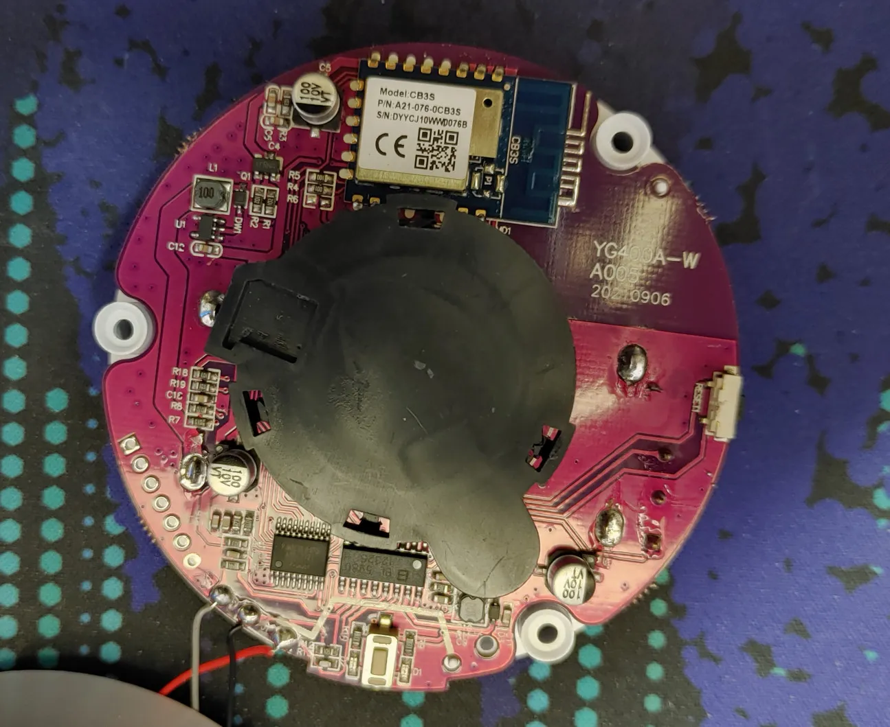
There is a newer versions with a CB3S module that can’t be flashed with Tasmota. It might be possible to replace it with a ESP-12 S/E/F. The model number on the PCB is YG400A-W. The solder mask is also purple instead of green.
Flashing
Device came with the latest Tuya firmware which cannot be Tuya-Converted at the time of writing (June 2020). To flash the device you will need to open it and solder to it. Due to the unfortunate placing of the photoelectric chamber you will have to use some other solder points instead of the trusty TYWE3S.
Connect the folowing:
- GND and RST to disable the MCU
- VCC and EN
- VCC, GND, TX and RX to your serial-to-USB adapter
- ground GPIO0 during boot
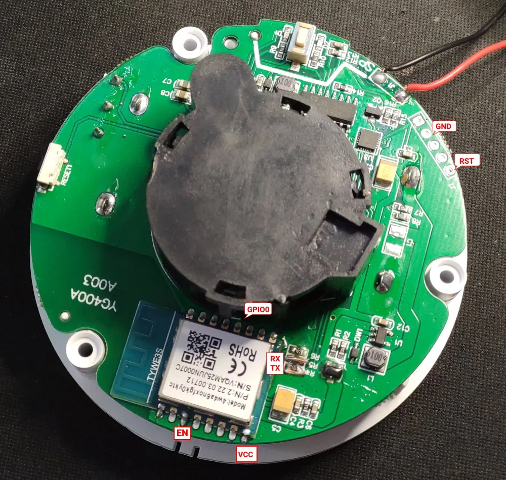
When finished you will have to remove the R4 and R5 resistors and bridge the pads or simply bridge them with solder and/or small wires. Without this Tasmota will not be able to communicate with the MCU properly.
Functions
dpID 1 smoke: 0 = clear / 1 = smoke detected
dpID 4 tamper alarm = 0 = ok / 1 = tampered
dpID 14 battery status: 0 = low / 1 = medium / 2 = high
Sensor uses the built in speaker as beeping alarm when dpId 1 is triggered.
The speaker and led on the test button are controlled by the MCU and there is no way to control them by software.
Configuration
Please read TuyaMCU article to understand the terminology and configuration process.
Change device to a TuyaMCU module (or apply the provided template, result is the same)
Module 54
Set the following configuration:
Backlog TuyaMCU 11,4; TuyaMCU 51,51
Functions
To get smoke detected alerts and battery status use rules to send data to custom topics. Battery status is sent rarely but I noticed it is always reported at first power on after batteries are replaced.
Rule1
  ON TuyaReceived#CmndData=0E04000102 DO publish2 stat/%topic%/BATT high ENDON
  ON TuyaReceived#Data=0E04000101 DO publish2 stat/%topic%/BATT medium ENDON
  ON TuyaReceived#Data=0E04000100 DO publish2 stat/%topic%/BATT low ENDON
  ON TuyaReceived#CmndData=0104000100 DO publish stat/%topic%/SMOKE OFF ENDON
  ON TuyaReceived#CmndData=0104000101 DO Publish stat/%topic%/SMOKE ON ENDON
Enable rule with Rule1 1
After smoke is detected the sensor rarely reports the off state so you will need to account for that in your home automation software since we cannot solve it with rules due to device shutting down after a few seconds.
Tamper status will be mapped to POWER1. ON is when the back lid is removed and OFF when the sensor is properly installed. You cannot control this state with the webUI.
Label webUI buttons
Backlog WebButton1 Tamper