


Available from:
Thepihut.com
Manufacturer:
Adafruit.com
| GPIO # | Component |
|---|---|
| GPIO00 | User |
| GPIO01 | Serial Tx |
| GPIO02 | Serial Rx |
| GPIO03 | None |
| GPIO04 | None |
| GPIO05 | User |
| GPIO06 | User |
| GPIO07 | ST7789 CS |
| GPIO08 | ??? |
| GPIO09 | User |
| GPIO10 | User |
| GPIO11 | User |
| GPIO12 | User |
| GPIO13 | User |
| GPIO14 | ??? |
| GPIO15 | ??? |
| GPIO16 | ??? |
| GPIO17 | ??? |
| GPIO18 | 74x595 SRCLK |
| GPIO19 | None |
| GPIO20 | None |
| GPIO21 | Output Hi |
| GPIO33 | WS2812 1 |
| GPIO34 | Output Hi |
| GPIO35 | SPI MOSI |
| GPIO36 | SPI CLK |
| GPIO37 | SPI MISO |
| GPIO38 | None |
| GPIO39 | ST7789 DC |
| GPIO40 | OLED Reset |
| GPIO41 | I2C SCL 1 |
| GPIO42 | I2C SDA 1 |
| GPIO43 | None |
| GPIO44 | None |
| GPIO45 | BkLight |
| GPIO46 | None |
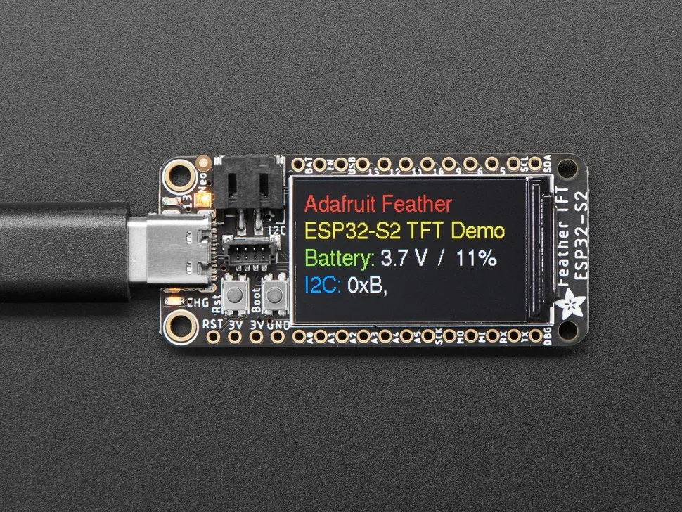
{"NAME":"Feather ESP32 S2 TFT","GPIO":[1,3200,3232,0,0,1,1,6592,7653,1,1,1,1,1,7652,7651,7650,7649,7648,0,0,3840,1376,3840,704,736,672,0,6624,1024,608,640,0,0,992,0],"FLAG":0,"BASE":1}A Feather form-factor ESP32-S2 dev board with an IPS ST7789V 1.14” display with 240x135 resolution.
This board uses an ESP32-S2-MINI-1-N4R2 module with 4 MB flash and 2 MB PSRAM.
When the board is booted into debug by holding BOOT and pressing the RESET button the USB port exposes a serial connection. This can be used to easily flash new firmware.
Flashing
Flash using Tasmota Web Installer and select Tasmota ESP32-S2 option.
For esptool.py download i.e. tasmota32s2.factory.bin and run esptool.py write_flash 0x0 tasmota32s2.factory.bin
To put ESP32-S2 in flash mode GPIO0 needs to be pulled low.
Device Notes


Peripherals
ST7789 TFT Display
The display works as expected with the tasmota32s2-display.bin firmware. These commands will help set up the display.
DisplayModel 15
DisplayWidth 240
DisplayHeight 135
DisplayRotate 3
This template sets up the display backlight as “Toggle 2”.
The board uses GPIO21 for power to the display so this template sets that pin to “Output Hi” to make sure that the display is powered on.
WS2818 Neopixel
This template sets up the WS2818 LED as a light, with “Toggle 1” controlling the LED’s power state.
The board uses GPIO34 for power to the LED so the template sets that to “Output Hi” so that the LED works.
LiPo Charging/Monitoring
This board has a 2-pin JST-PH battery connector and a LIPO charging circuit built in. This circuit uses an MCP73831 fpr automatic charge/discharge management and a LC709203 battery monitor on the I2C bus.
Although LC709203 isn’t supported by Tasmota this board works fine with Tasmota running on battery power.
BMEx80 (unpopulated)
Its possible to add a BMEx80 (BME280 or BME680) by manually soldering one onto available pads on the bottom of the board, but this isn’t included from the factory.
As long as GPIO21 is high (powering on the display and I2C bus) this should work fine with Tasmota if the chip is soldered on.
STEMMA-QT / QWIIC Connector
A 4-pin JST-SH socket on the board allows for quick attachment of I2C sensors and other devices. This board uses 3.3v logic so this connector is compatible with QWIIC as well.
Debug Console Output
The bottom-right corner pin, labeled DBG, is attached to the ESP32-S2’s debug serial output. It isn’t useful within Tasmota but can be helpful for development, troubleshooting, or data logging.