


Available from:
Manufacturer:
Adafruit.com
Install method:
USB to Serial
| GPIO # | Component |
|---|---|
| GPIO00 | None |
| GPIO01 | None |
| GPIO02 | None |
| GPIO03 | I2C SDA 1 |
| GPIO04 | I2C SCL 1 |
| GPIO05 | User |
| GPIO06 | User |
| GPIO07 | Output Hi |
| GPIO08 | User |
| GPIO09 | User |
| GPIO10 | User |
| GPIO11 | User |
| GPIO12 | User |
| GPIO13 | User |
| GPIO14 | User |
| GPIO15 | User |
| GPIO16 | User |
| GPIO17 | User |
| GPIO18 | User |
| GPIO19 | None |
| GPIO20 | None |
| GPIO21 | Output Hi |
| GPIO33 | WS2812 1 |
| GPIO34 | None |
| GPIO35 | User |
| GPIO36 | User |
| GPIO37 | User |
| GPIO38 | User |
| GPIO39 | User |
| GPIO40 | None |
| GPIO41 | None |
| GPIO42 | None |
| GPIO43 | None |
| GPIO44 | None |
| GPIO45 | None |
| GPIO46 | None |
| GPIO47 | None |
| GPIO48 | None |
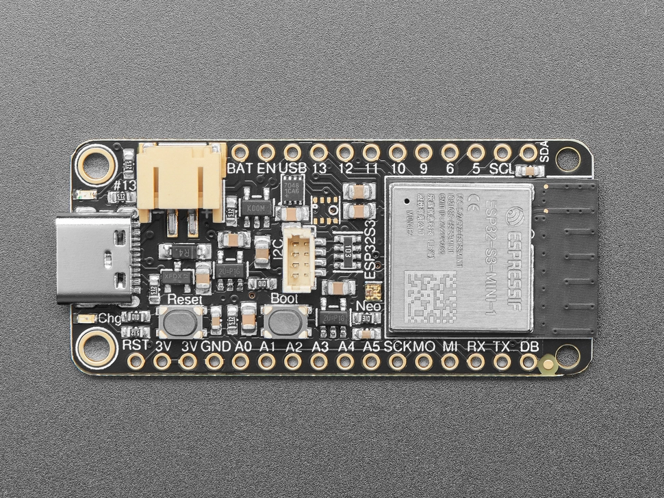
{"NAME":"ESP32-S3 Feather","GPIO":[0,0,0,640,608,1,1,3840,1,1,1,1,1,1,1,1,1,1,1,0,0,3840,1376,0,1,1,1,1,1,0,0,0,0,0,0,0,0,0],"FLAG":0,"BASE":1}A Feather form factor ESP32-S3 dev board with 1S LiPo battery monitoring.
This board uses an ESP32-S3-MINI-1-P1N8 module with 8MB of flash and no PSRAM.
When the board is booted into debug by holding BOOT and pressing the RESET button the USB-Serial chip on the USB port exposes a serial connection. This can be used to easily flash new firmware.
Flashing
Flash using Tasmota Web Installer and select Tasmota ESP32-S3 option.
For esptool.py download f.e. tasmota32s3.factory.bin and run esptool.py write_flash 0x0 tasmota32s3.factory.bin
To put ESP32-S3 in flash mode GPIO0 needs to be pulled low.
Device Notes


Peripherals
WS2812BNeopixel- On
GPIO33(configured asWS2812) with power onGPIO21(configured asOutput Hi).
- On
- STEMMA-QT JST-SH I2C bus connector
GPIO3(SDA) andGPIO4(SCL) (configured asI2C 1) andGPIO7for power (configured asOutput Hi). This ports are on the same bus as theSCLandSDApins labeled on the board.