Available from:
Amazon.com
Amazon.com
Digikey.com
Mou.sr
Manufacturer:
Adafruit.com
Install method:
USB to Serial
| GPIO # | Component |
|---|---|
| GPIO00 | None |
| GPIO01 | None |
| GPIO02 | None |
| GPIO03 | None |
| GPIO04 | ??? |
| GPIO05 | None |
| GPIO09 | User |
| GPIO10 | User |
| GPIO12 | User |
| GPIO13 | Led 1 |
| GPIO14 | User |
| GPIO15 | User |
| GPIO16 | User |
| GPIO17 | User |
| GPIO18 | None |
| GPIO19 | User |
| GPIO20 | None |
| GPIO21 | None |
| GPIO22 | I2C SCL 1 |
| GPIO23 | I2C SDA 1 |
| GPIO24 | None |
| GPIO25 | ADC Input 2 |
| GPIO26 | ADC Input 1 |
| GPIO27 | User |
| GPIO6 | None |
| GPIO7 | None |
| GPIO8 | None |
| GPIO11 | None |
| GPIO32 | User |
| GPIO33 | User |
| GPIO34 | ADC Input 3 |
| GPIO35 | ??? |
| GPIO36 | ??? |
| GPIO37 | None |
| GPIO38 | None |
| GPIO39 | ADC Input 4 |
{"NAME":"HUZZAH32","GPIO":[0,0,0,0,4709,0,1,1,1,288,1,1,1,1,0,1,0,0,608,640,0,4705,4704,1,0,0,0,0,1,1,4706,4710,4708,0,0,4707],"FLAG":0,"BASE":1}Template Notes
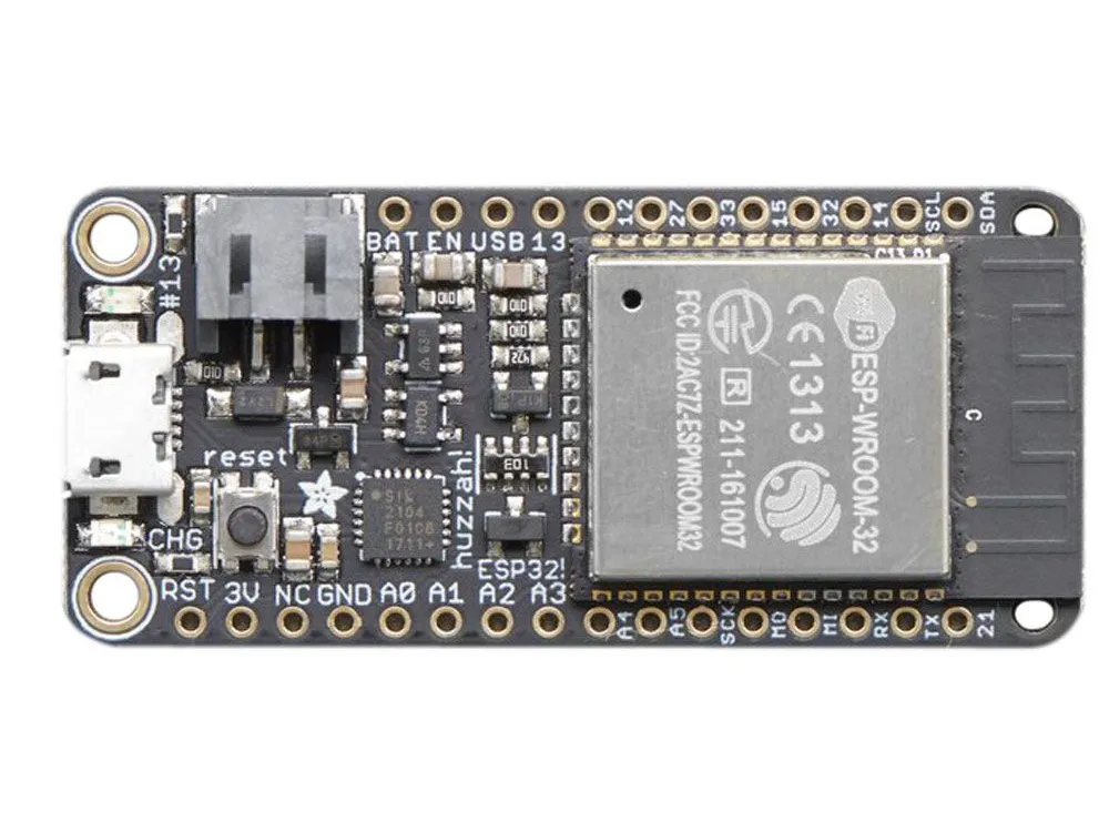
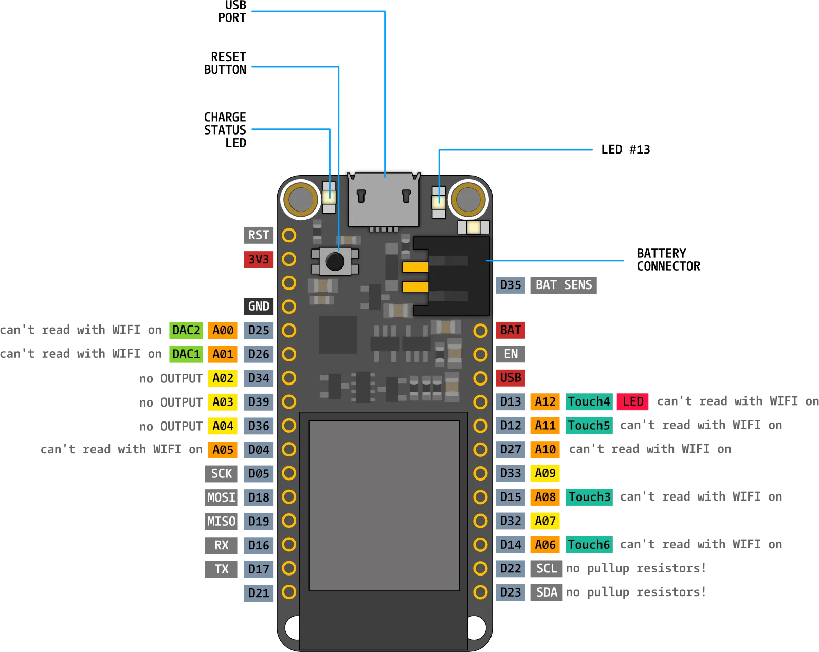
The provided template sets up the I2C pins (GPIO22/SCL, GPIO23/SDA) as well as 7 ADCs for the pins labeled A0-A5 on the board and the VBAT sensor. GPIO13 is set as an LED for the board’s red indicator LED but can also be used as a GPIO or ADC input if needed.
Device Notes
The board has a resistive divider connected to VBAT that goes into pin GPIO35/ADC1_7. VBAT is available on a 2-pin JST header as well as the BAT pin next to it and is intended to be used with a 4.2V/3.7V LiPo or LiIon battery.
This isn’t useful for Tasmota but for power saving purposes the built-in 3.3V regulator can be disabled by pulling the EN pin to ground. This will power down the ESP32 module and everything else on the board aside from the USB to UART converter.


