


Available from:
Manufacturer:
Adafruit.com
Install method:
USB to Serial
| GPIO # | Component |
|---|---|
| GPIO00 | WS2812 1 |
| GPIO01 | None |
| GPIO02 | Output Hi |
| GPIO03 | None |
| GPIO04 | User |
| GPIO05 | User |
| GPIO09 | None |
| GPIO10 | None |
| GPIO12 | User |
| GPIO13 | User |
| GPIO14 | User |
| GPIO15 | User |
| GPIO16 | None |
| GPIO17 | None |
| GPIO18 | None |
| GPIO19 | User |
| GPIO20 | I2C SCL 1 |
| GPIO21 | User |
| GPIO22 | I2C SDA 1 |
| GPIO23 | None |
| GPIO24 | None |
| GPIO25 | User |
| GPIO26 | User |
| GPIO27 | User |
| GPIO6 | None |
| GPIO7 | User |
| GPIO8 | User |
| GPIO11 | None |
| GPIO32 | User |
| GPIO33 | User |
| GPIO34 | User |
| GPIO35 | ADC Input 1 |
| GPIO36 | User |
| GPIO37 | User |
| GPIO38 | None |
| GPIO39 | User |
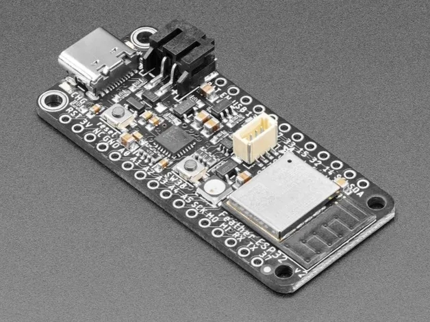
{"NAME":"HUZZAH32v2","GPIO":[1376,0,3840,0,1,1,0,0,1,1,1,1,0,0,0,1,608,1,640,0,0,1,1,1,0,1,1,0,1,1,1,4704,1,1,0,1],"FLAG":0,"BASE":1}A Feather form factor ESP32 dev board with battery management.
This board uses an ESP32-PICO-MINI-02-N8R2 module with 8MB of flash and 2MB of PSRAM.
The board also includes a CP2102N USB-Serial chip on the USB port for easy device flashing and debug console output access.
Flashing
When the board is booted into debug by holding BOOT and pressing the RESET button the USB-Serial chip on the USB port exposes a serial connection. This can be used to easily flash new firmware.
For flashing via tasmota32.factory.bin, download the tasmota32.factory.bin file.
esptool.py --chip esp32 --baud 115200 --before default_reset --after hard_reset write_flash --erase-all -z 0x0 tasmota32.factory.bin
Device Notes


Peripherals
WS2812BNeopixel- On
GPIO0(configured asWS2812) with power onGPIO2(configured asOutput Hi)
- On
- STEMMA-QT JST-SH I2C bus connector
- On
GPIO20(SCL) andGPIO22(SDA), bus shared withSCL/SDApins on board. (Configured asI2C 1)
- On
- 1S LiPo battery management subsystem with 2-pin JST-PH connector
- Battery voltage divider on
GPIO35. (Configured asAnalog1)
- Battery voltage divider on
GPIO Pin Mapping
The user pins labelled on the board are set up as User pins in the template, allowing module configuration. This is a quick reference to map the pin label on the board to the module user pin.
| Label | GPIO |
|---|---|
A0 |
GPIO26 |
A1 |
GPIO25 |
A2 |
GPIO34 |
A3 |
GPIO39 |
A4 |
GPIO36 |
A5 |
GPIO34 |
SCK |
GPIO5 |
MOSI |
GPIO19 |
MISO |
GPIO21 |
RX |
GPIO8 |
TX |
GPIO7 |
I37 |
GPIO37 |
SDA |
GPIO22 |
SCL |
GPIO20 |
IO14 |
GPIO14 |
IO32 |
GPIO32 |
IO15 |
GPIO15 |
IO33 |
GPIO33 |
IO27 |
GPIO27 |
IO12 |
GPIO12 |
IO13 |
GPIO13 |