


Available from:
Digikey.com
Shop.pimoroni.com
Eckstein-shop.de
Manufacturer:
Adafruit.com
Install method:
USB to Serial
| GPIO # | Component |
|---|---|
| GPIO00 | None |
| GPIO01 | WS2812 1 |
| GPIO02 | None |
| GPIO03 | ADC Input 2 |
| GPIO04 | ADC Input 1 |
| GPIO05 | None |
| GPIO06 | None |
| GPIO07 | None |
| GPIO08 | None |
| GPIO09 | None |
| GPIO10 | User |
| GPIO11 | Button 4 |
| GPIO12 | Button 3 |
| GPIO13 | Led 1 |
| GPIO14 | Button 2 |
| GPIO15 | Button 1 |
| GPIO16 | Output Hi |
| GPIO17 | Buzzer |
| GPIO18 | User |
| GPIO19 | None |
| GPIO20 | None |
| GPIO21 | Output Lo |
| GPIO33 | I2C SCL 1 |
| GPIO34 | I2C SCL 1 |
| GPIO35 | SSPI MOSI |
| GPIO36 | SSPI SCLK |
| GPIO37 | SSPI MISO |
| GPIO38 | None |
| GPIO39 | None |
| GPIO40 | None |
| GPIO41 | None |
| GPIO42 | None |
| GPIO43 | None |
| GPIO44 | None |
| GPIO45 | None |
| GPIO46 | None |
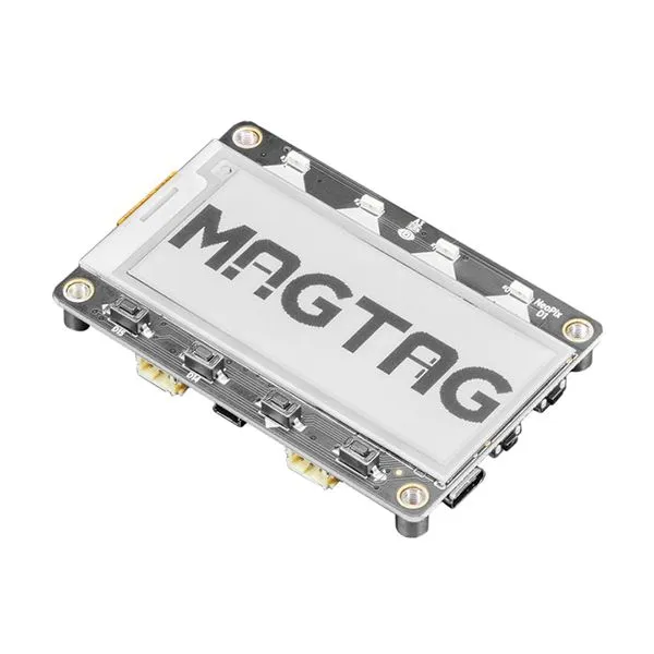
{"NAME":"MagTag","GPIO":[0,1376,0,4705,4704,0,0,0,0,0,1,35,34,288,33,32,3840,480,1,0,0,3872,608,608,864,896,832,0,0,0,0,0,0,0,0,0],"FLAG":0,"BASE":1}An ESP32-S2 dev board with a 2.9” E-Paper display, various peripherals, and standard GPIO/I2C connectors for rapid prototyping.
This board uses an ESP32-S2-WROVER module with 4 MB flash and 2 MB PSRAM.
When the board is booted into debug by holding BOOT and pressing the RESET button the USB port exposes a serial connection. This can be used to easily flash new firmware.
Flashing
Flash using Tasmota Web Installer and select Tasmota ESP32-S2 option.
For esptool.py download i.e. tasmota32s2.factory.bin and run esptool.py write_flash 0x0 tasmota32s2.factory.bin
To put ESP32-S2 in flash mode GPIO0 needs to be pulled low.
Device Notes


Peripherals
- 2.9” 291x128 SPI E-Paper Display (
IL0373controller)- Not currently supported by Tasmota
- 4x Front Panel User Buttons
- On
GPIO11-12andGPIO14-15(configured asButton 1-4, left to right)
- On
- 4x
WS2812BNeopixel- On
GPIO1(configured asWS2812) with power onGPIO21(configured asOutput Low).
- On
- Back panel red status LED
- On
GPIO13(configured asLED 1)
- On
- Analog light sensor
- On
GPIO3(configured asAnalog 2) with power onGPIO21(already set toOutput Lowfor NeoPixels)
- On
- PWM-capable Buzzer
- On
GPIO17(configured asBuzzer) with power/enable onGPIO16(configured asOutput Hi). - Use
BuzzerPWMconsole command to switch to PWM mode
- On
- 3-axis Accelerometer ((
LIS3DH](https://www.st.com/resource/en/datasheet/lis3dh.pdf))- On I2C bus, interrupt on
GPIO9(not currently supported by Tasmota)
- On I2C bus, interrupt on
- 2x 3-pin STEMMA JST-PH GPIO connectors
- On
GPIO18(A1) andGPIO10(D10) (both configured asUserfor setup via module)
- On
- STEMMA-QT JST-SH I2C bus connector
- Both ports share the same bus, on
GPIO33(SCL) andGPIO34(SDA) (configured asI2C 1).
- Both ports share the same bus, on
- 1S LiPo battery management subsystem with 2-pin JST-PH connector
- Battery voltage divider on
GPIO4(configured asAnalog 1)
- Battery voltage divider on