


Available from:
Manufacturer:
Adafruit.com
Install method:
USB to Serial
| GPIO # | Component |
|---|---|
| GPIO00 | Button 1 |
| GPIO01 | Serial Tx |
| GPIO02 | None |
| GPIO03 | Serial Rx |
| GPIO04 | User |
| GPIO05 | WS2812 1 |
| GPIO09 | None |
| GPIO10 | None |
| GPIO12 | User |
| GPIO13 | User |
| GPIO14 | User |
| GPIO15 | User |
| GPIO16 | None |
| GPIO17 | None |
| GPIO18 | None |
| GPIO19 | I2C SCL 1 |
| GPIO20 | None |
| GPIO21 | None |
| GPIO22 | I2C SDA 1 |
| GPIO23 | None |
| GPIO24 | None |
| GPIO25 | User |
| GPIO26 | User |
| GPIO27 | User |
| GPIO6 | None |
| GPIO7 | User |
| GPIO8 | Output Hi |
| GPIO11 | None |
| GPIO32 | User |
| GPIO33 | User |
| GPIO34 | None |
| GPIO35 | None |
| GPIO36 | None |
| GPIO37 | None |
| GPIO38 | None |
| GPIO39 | None |
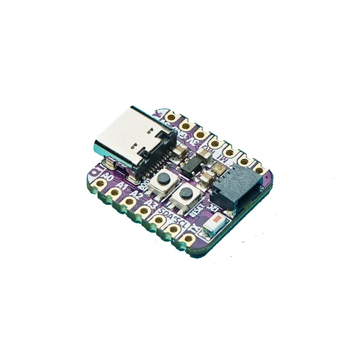
{"NAME":"QTPy ESP32 Pico","GPIO":[32,3200,0,3232,1,1376,0,0,1,1,1,1,0,0,0,608,0,0,640,0,0,1,1,1,0,1,3840,0,1,1,0,0,0,0,0,0],"FLAG":0,"BASE":1}An ESP32 Pico dev board in the tiny (22mm x 17.9mm) Seeduino XIAO form factor.
This board uses an ESP32 Pico V3 02 chip with two cores, 8 MB of flash and 2 MB of PSRAM.
The board also includes a CP2102N USB-Serial chip on the USB port for easy device flashing and debug console output access.
Flashing
When the board is booted into debug by holding BOOT and pressing the RESET button the USB-Serial chip on the USB port exposes a serial connection. This can be used to easily flash new firmware.
For flashing via tasmota32.factory.bin, download the tasmota32.factory.bin file.
esptool.py --chip esp32 --baud 115200 --before default_reset --after hard_reset write_flash --erase-all -z 0x0 tasmota32.factory.bin
Device Notes


Peripherals
WS2812BNeopixel- On
GPIO5with power onGPIO8. - Provided template configures this as
WS2812withGPIO8asOutput Hifor power.
- On
- 1x front panel user button
- On
GPIO0(doubles asBOOT0button) - Provided template configures this as
Button 1.
- On
- STEMMA-QT JST-SH I2C bus connector
- On
GPIO19(SCL) andGPIO22(SDA), bus shared with onboard sensors. - Provided template configures this as
I2C 1.
- On
GPIO Pin Mapping
The user pins labelled on the board are set up as User pins in the template, allowing module configuration. This is a quick reference to map the pin label on the board to the module user pin.
| Label | GPIO |
|---|---|
A0 |
GPIO26 |
A1 |
GPIO25 |
A2 |
GPIO27 |
A3 |
GPIO15 |
SDA |
GPIO4 |
SCL |
GPIO33 |
TX |
GPIO32 |
RX |
GPIO7 |
SCK |
GPIO14 |
MISO |
GPIO12 |
MOSI |
GPIO13 |