


Available from:
Manufacturer:
Adafruit.com
Install method:
USB to Serial
| GPIO # | Component |
|---|---|
| GPIO00 | Button_i 1 |
| GPIO01 | None |
| GPIO02 | None |
| GPIO03 | None |
| GPIO04 | None |
| GPIO05 | User |
| GPIO06 | User |
| GPIO07 | User |
| GPIO08 | User |
| GPIO09 | User |
| GPIO10 | None |
| GPIO11 | None |
| GPIO12 | None |
| GPIO13 | None |
| GPIO14 | None |
| GPIO15 | None |
| GPIO16 | User |
| GPIO17 | User |
| GPIO18 | User |
| GPIO19 | None |
| GPIO20 | None |
| GPIO21 | None |
| GPIO33 | None |
| GPIO34 | None |
| GPIO35 | User |
| GPIO36 | User |
| GPIO37 | User |
| GPIO38 | Output Hi |
| GPIO39 | WS2812 1 |
| GPIO40 | I2C SCL 1 |
| GPIO41 | I2C SDA 1 |
| GPIO42 | None |
| GPIO43 | None |
| GPIO44 | None |
| GPIO45 | None |
| GPIO46 | None |
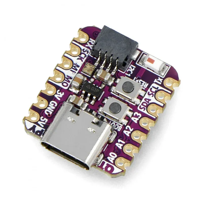
{"NAME":"QTPy ESP32-S2","GPIO":[96,0,0,0,0,1,1,1,1,1,0,0,0,0,0,0,1,1,1,0,0,0,0,0,1,1,1,3840,1376,608,640,0,0,0,0,0],"FLAG":0,"BASE":1}An ESP32-S2 dev board in the tiny (22mm x 17.9mm) Seeduino XIAO form factor.
This board uses an ESP32-S2F-N4R2 chip with 4 MB of flash and 2 MB of PSRAM.
When the board is booted into debug by holding BOOT and pressing the RESET button the USB-Serial chip on the USB port exposes a serial connection. This can be used to easily flash new firmware.
Flashing
Flash using Tasmota Web Installer and select Tasmota ESP32-S2 option.
For esptool.py download i.e. tasmota32s2.factory.bin and run esptool.py write_flash 0x0 tasmota32s2.factory.bin
To put ESP32-S2 in flash mode GPIO0 needs to be pulled low.
Device Notes


Peripherals
WS2812BNeopixel- On
GPIO39with power onGPIO38. - Provided template configures this as
WS2812withGPIO38asOutput Hifor power.
- On
- 1x front panel user button
- On
GPIO0(doubles asBOOT0button) - Provided template configures this as
Button 1.
- On
- STEMMA-QT JST-SH I2C bus connector
- On
GPIO40(SCL) andGPIO41(SDA), on a separate I2C bus from the pins labeled SCL/SDA on the board. - Provided template configures this as
I2C 1.
- On
GPIO Pin Mapping
The user pins labelled on the board are set up as User pins in the template, allowing module configuration. This is a quick reference to map the pin label on the board to the module user pin.
| Label | GPIO |
|---|---|
A0 |
GPIO18 |
A1 |
GPIO17 |
A2 |
GPIO9 |
A3 |
GPIO8 |
SDA |
GPIO7 |
SCL |
GPIO6 |
TX |
GPIO5 |
RX |
GPIO16 |
SCK |
GPIO36 |
MISO |
GPIO37 |
MOSI |
GPIO35 |