


Available from:
Digikey.com
Digikey.com
Manufacturer:
Adafruit.com
| GPIO # | Component |
|---|---|
| GPIO00 | Button 1 |
| GPIO01 | User |
| GPIO02 | User |
| GPIO03 | Button_id 2 |
| GPIO04 | Button_id 3 |
| GPIO05 | Button_id 4 |
| GPIO06 | User |
| GPIO07 | User |
| GPIO08 | User |
| GPIO09 | User |
| GPIO10 | User |
| GPIO11 | User |
| GPIO12 | User |
| GPIO13 | User |
| GPIO14 | User |
| GPIO15 | User |
| GPIO16 | User |
| GPIO17 | User |
| GPIO18 | ADC Input 1 |
| GPIO19 | None |
| GPIO20 | None |
| GPIO21 | BkLight |
| GPIO33 | I2C SCL 1 |
| GPIO34 | I2C SDA 1 |
| GPIO35 | SSPI MOSI |
| GPIO36 | SSPI SCLK |
| GPIO37 | User |
| GPIO38 | None |
| GPIO39 | ST7789 DC |
| GPIO40 | ST7789 CS |
| GPIO41 | OLED Reset |
| GPIO42 | Buzzer |
| GPIO43 | None |
| GPIO44 | None |
| GPIO45 | None |
| GPIO46 | None |
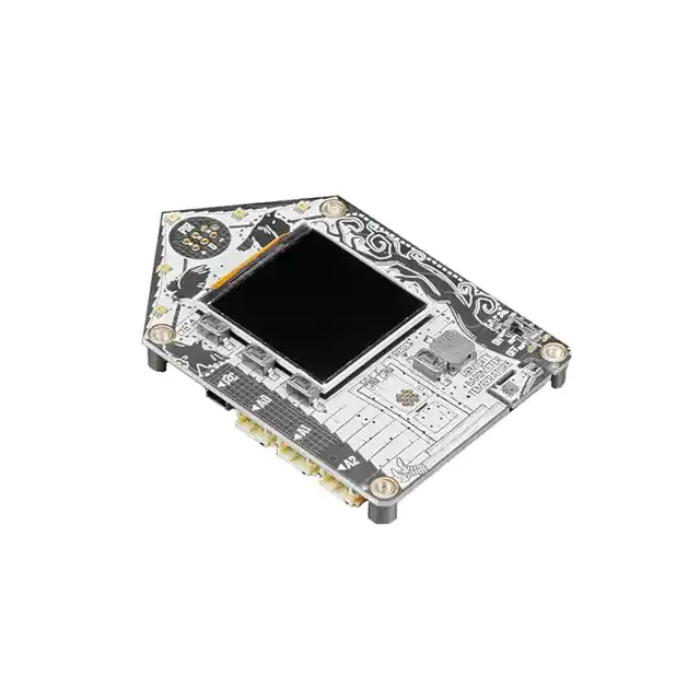
{"NAME":"Funhouse","GPIO":[32,1,1,7713,7714,7715,1,1,1,1,1,1,1,1,1,1,1,1,4704,0,0,992,608,640,864,896,1,0,6624,6592,1024,480,0,0,0,0],"FLAG":0,"BASE":1}An IoT-focused ESP32-S2 dev board with a display, a variety of on-board peripherals, and standard GPIO/I2C connectors for rapid experimentation and development.
This board uses an ESP32-S2-WROVER module with 4 MB flash and 2 MB PSRAM.
When the board is booted into debug by holding BOOT (on the back) and pressing the RESET button (on the front) the USB port exposes a serial connection. This can be used to easily flash new firmware.
Flashing
Flash using Tasmota Web Installer and select Tasmota ESP32-S2 option.
For esptool.py download i.e. tasmota32s2.factory.bin and run esptool.py write_flash 0x0 tasmota32s2.factory.bin
To put ESP32-S2 in flash mode GPIO0 needs to be pulled low.
Device Notes


Peripherals
- 240x240 ST7789-based SPI TFT display
- Supported by Tasmota in
-displayfirmware and viaUSE_ST7789in custom firmware.
- Supported by Tasmota in
- AHT20 I2C temp/humidity sensor
- Supported by Tasmota in
-sensorsfirmware and viaUSE_AHT2xin custom firmware.
- Supported by Tasmota in
- DP310 I2C temp/pressure sensor
- Currently unsupported by Tasmota.
- ALS-PT19 analog light sensor
- On
GPIO18 - Provided template configures this as
ADC Input 1
- On
- A front-facing mini PIO sensor socket
- On
GPIO16 - Provided template configures this as a
Userpin for manual configuration via module.
- On
- 3 front panel user buttons, one back panel user button
- Front panel buttons on
GPIO3-5 - Back panel button on
GPIO0(doubles asBOOT0button) - Provided template configures these as
Button 1-4, with the rear panel asButton 1.
- Front panel buttons on
- 7 front panel capacitive touch buttons
- On
GPIO6-13 - Limited support in Tasmota, only 4 of the 7 can be used. Provided template sets these up as
Userpins for manual configuration via module.
- On
- 5 APA102 DotStar LEDs
- On
GPIO15(Clock) andGPIO14(Data) - Currently unsupported by Tasmota, support requested via Github Discussions.Provided template sets these up as
Userpins for manual configuration via module.
- On
- One front panel red LED
- On
GPIO37 - Provided template configures this as
Led 1.
- On
- GPIO-connected buzzer
- On
GPIO42 - Provided template sets configures this as
Buzzer
- On
- 3x 2-pin STEMMA JST-PH GPIO connectors
- On
GPIO20(A0),GPIO2(A1), andGPIO1(A2) - Provided template configures these as
Userpins for manual configuration via module.
- On
- STEMMA-QT JST-SH I2C bus connector
- On
GPIO33(SCL) andGPIO34(SDA), bus shared with onboard sensors.
- On
Debug Console Output
The ESP32-S2 serial debug console is available on two test pads on the back of the board, in a cluster of three test pads to the left of the ESP32-S2 module. The TX signal is on the top-left pad with RX on the top-right pad.
