Available from:
Amazon.de
Install method:
USB to Serial
| GPIO # | Component |
|---|---|
| GPIO00 | LedLink |
| GPIO01 | None |
| GPIO02 | Led2 |
| GPIO03 | Button3 |
| GPIO04 | Relay3 |
| GPIO05 | Button2 |
| GPIO09 | None |
| GPIO10 | None |
| GPIO12 | Button1 |
| GPIO13 | Relay1 |
| GPIO14 | Led3 |
| GPIO15 | Relay2 |
| GPIO16 | Led1 |
| FLAG | None |
{"NAME":"Anccy Shutter","GPIO":[157,0,53,19,23,18,0,0,17,21,54,22,52],"FLAG":0,"BASE":18}
Relays / Buttons
- Relay/Button 1: up (upper button)
- Relay/Button 2: down (lower button)
- Relay/button 3: stop (middle button)
Main Config
Template
template {"NAME":"Anccy Shutter","GPIO":[157,0,53,19,23,18,0,0,17,21,54,22,52],"FLAG":0,"BASE":18}module 0
MQTT / Names
Topic anccyFriendlyName AnccyDeviceName Anccy
Main Options
SetOption80 1# Enable Shutter SupportInterLock 1,2# Lock Relay 1/2 to be set parallelInterLock on# enable LockShutterButton1 1 up 1# define Button for UPShutterButton1 2 down 1# define Button for DownPulsetime3 30# Set Power on Button 3 to 3s (show LED for 3s)WebButton3 ■# Set stop symbol for the third button in the web GUIPowerOnState 0# keep relay(s) OFF after power uprule1 ON Power3#State=1 DO ShutterStop1 ENDON# Button 3 (Power 3) stops shutterrule1 on
All Together
First part:
Backlog template {"NAME":"Anccy Shutter","GPIO":[157,0,53,19,23,18,0,0,17,21,54,22,52],"FLAG":0,"BASE":18}; module 0; Topic anccy; FriendlyName Anccy; DeviceName Anccy
Second part:
Backlog SetOption80 1; InterLock 1,2; InterLock on; ShutterButton1 1 up 1; ShutterButton1 2 down 1; Pulsetime3 30; WebButton3 ■; PowerOnState 0; rule1 ON Power3#State=1 DO ShutterStop1 ENDON; rule1 on
Timer(s) and Rule for Timers
For this config to work, you have to set Latitude/Longitude (sunrise/sunset) and have the correct time set.
To be able to set correct timer times, you also should set TimeSTD/TimeDST (daylight saving time) as well as Timezone.
Timers on# Enable TimersTimer1 {"Enable":1,"Mode":1,"Time":"00:00","Window":0,"Days":"1111111","Repeat":1,"Output":1,"Action":3}# SunriseTimer2 {"Enable":1,"Mode":2,"Time":"00:00","Window":0,"Days":"1111111","Repeat":1,"Output":1,"Action":3}# Sunsetrule2 ON Clock#Timer=1 DO ShutterOpen ENDON# Rule for Timer1 (Sunrise) - Openrule2 +ON Clock#Timer=2 DO ShutterClose ENDON# Rule for Timer2 (Sunset) - Closerule2 on
All Together
Backlog Timers on; Timer1 {"Enable":1,"Mode":1,"Time":"00:00","Window":0,"Days":"1111111","Repeat":1,"Output":1,"Action":3}; Timer2 {"Enable":1,"Mode":2,"Time":"00:00","Window":0,"Days":"1111111","Repeat":1,"Output":1,"Action":3}; rule1 on; rule2 on; rule2 ON Clock#Timer=1 DO ShutterOpen ENDON ON Clock#Timer=2 DO ShutterClose ENDON
Calibration
Tasmota Documentation
ShutterOpenDuration1 17.8# Stopwatch :)ShutterCloseDuration1 16.2# Stopwatch :)ShutterSetHalfway1 63# Close -> Set manual to 50% open -> ShutterPositionShutterEnableEndStopTime 1# Give 1 seconds additional motor movement on end positions
The values are only examples!
There is an issue with ShutterSetHalfway1 from v8.5.1:
ShutterCalibrationis set to odd values and the whole calibration does not work.- This seems to be fixed in v9.1.0
Special configuration
Use the middle button for stopping and disabling automatic timer (on holding middle button).
- Observations show, that stop has now some more delay - reason unknown
- Stop in WEB GUI does not work as
Power3is not evaluated for stop actionPower3/LED3is now used to show timer state- Workaround: press UP/DOWN while shutter is in movement to stop
Some Settings
mem1 1# Set Enable Automaticmem2 30# Default Blink Delay (3s)SetOption32 20# Hold Time (2s)Pulsetime3 0# Set Power on Button 3 no pulse –> controlled by rule(s)InterLock 1,2# only reay 1/2 in InterLock
Rule for Timer / LED Management
rule1 ON Button3#State=2 DO Backlog ShutterStop1; Power3 toggle; RuleTimer1 2 ENDON# Single Press Button3 (middle) –> Stop Shutter, RuleTimer 3 sec.rule1 +ON Button3#State=3 DO event togglemem1=%mem1% ENDON# HOLD Button3 (middle) –> event togglemem1rule1 +ON Rules#Timer=1 DO var1 %var1% ENDON# RuleTimer for LED –> Rewrite var11rule1 +ON event#togglemem1=0 DO mem1 1 ENDON# Toggle mem1 from 0 to 1 (mem1 == 1 –> automatic)rule1 +ON event#togglemem1=1 DO mem1 0 ENDON# Toggle mem1 from 1 to 0 (mem1 == 0 –> manual)rule1 +ON mem1#State DO Backlog var1 %mem1%; Sub1 %var2% ENDON# Set var1 to mem1 - substract var2 (NTP status)rule1 +ON var2#State DO Backlog var1 %mem1%; Sub1 %var2% ENDON# Set var1 to mem1 - substract var2 (NTP status)rule1 +ON var1#State<1 DO Backlog Power3 on; Rule2 off ENDON# var1 < 1 –> LED3 off (done by Power3), Rule2 (Timer) onrule1 +ON var1#State==1 DO Backlog Power3 off; Rule2 on ENDON# var1 == 1 –> LED3 on (done by Power3), Rule2 (Timer) offrule1 +ON var2#State DO event blink=%value% ENDON# Start/Stop Blink on var2 changerule1 +ON event#blink=1 DO Backlog delay %mem2%; Power3 toggle; event blink=%var2% ENDON# Blink eventrule1 +ON System#Init DO var2 1 ENDON# At Boot: var2 == 1 –> NTP not setrule1 +ON Time#Initialized DO var2 0 ENDON# Afer NTP set: var2 == 0 –> NTP setrule1 on
All Together
First part:
Backlog mem1 1; mem2 30; SetOption32 20; Pulsetime3 0; Interlock 1,2
Second part:
rule1 ON Button3#State=2 DO Backlog ShutterStop1; Power3 toggle; RuleTimer1 2 ENDON ON Button3#State=3 DO event togglemem1=%mem1% ENDON ON Rules#Timer=1 DO var1 %var1% ENDON ON event#togglemem1=0 DO mem1 1 ENDON ON event#togglemem1=1 DO mem1 0 ENDON ON mem1#State DO Backlog var1 %mem1%; Sub1 %var2% ENDON ON var2#State DO Backlog var1 %mem1%; Sub1 %var2% ENDON ON var1#State<1 DO Backlog Power3 on; Rule2 off ENDON ON var1#State==1 DO Backlog Power3 off; Rule2 on ENDON ON var2#State DO event blink=%value% ENDON ON event#blink=1 DO Backlog delay %mem2%; Power3 toggle; event blink=%var2% ENDON ON System#Init DO var2 1 ENDON ON Time#Initialized DO var2 0 ENDON
Flashing with serial
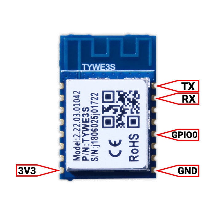
System is based on TYWE3S module. TuyaConvert isn’t working (Issue and collaboration). You have to use serial flashing.
Pictures
Top:
 Bottom:
 Module Pinout:

Flash
You have to cut the RX connection on the bottom of the pcb. RX is connected to the middle touch button. Without cutting, flash does not work.
Pinout
 .
.


