


Available from:
Amazon.com
Aliexpress.com
Walmart.ca
Manufacturer:
Alibaba.com
Install method:
USB to Serial
| GPIO # | Component |
|---|---|
| GPIO00 | Led1i |
| GPIO01 | None |
| GPIO02 | Led2i |
| GPIO03 | None |
| GPIO04 | Relay1 |
| GPIO05 | BL0937 CF |
| GPIO09 | None |
| GPIO10 | None |
| GPIO12 | HLWBL SELi |
| GPIO13 | Button1 |
| GPIO14 | HLWBL CF1 |
| GPIO15 | None |
| GPIO16 | None |
| FLAG | None |
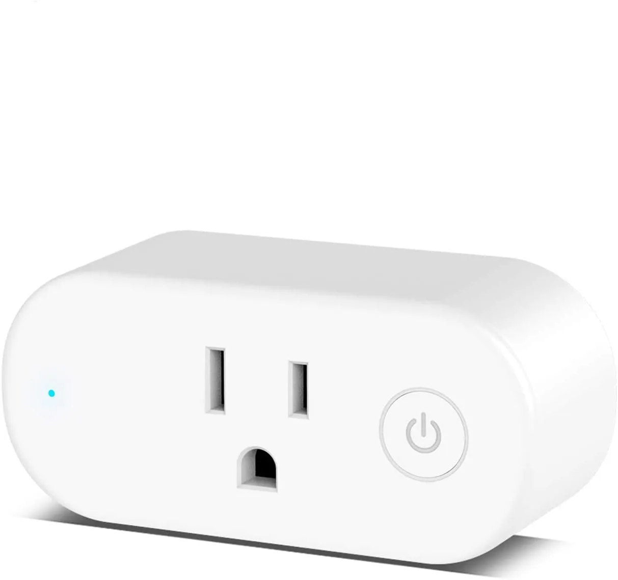
{"NAME":"Aoycocr X10S","GPIO":[56,0,57,0,21,134,0,0,131,17,132,0,0],"FLAG":0,"BASE":45}As of September 20, 2020, a four-pack of these plugs ordered from Amazon.com is not able to install tasmota using the tuya-convert utility. The exterior of these plug is slightly different than in the pictures, above. On the front of the plug the placement of the button and LED has changed.
Units bought December 13, 2020 can be programmed by serial port, but getting to the TX/RX and GPIO pins are tricky. The easiest access is on the bottom of the main board, but the power prongs are soldered to the board and difficult to remove without melting the plastic. In addition, the units are glued closed with no plastic prongs holding the shell together. Using a blade to open the units is relatively easy, but the units won’t go back together without new glue.
Instead, I used a dremel tool to cut out a portion of the back panel. I plan to use hot glue to close the back up. Close the unit back up safely before using the plug. Images below.

And the writing on the bottom (plug side) has changed:

Here are some pictures of the internals of this plug. First an overview:

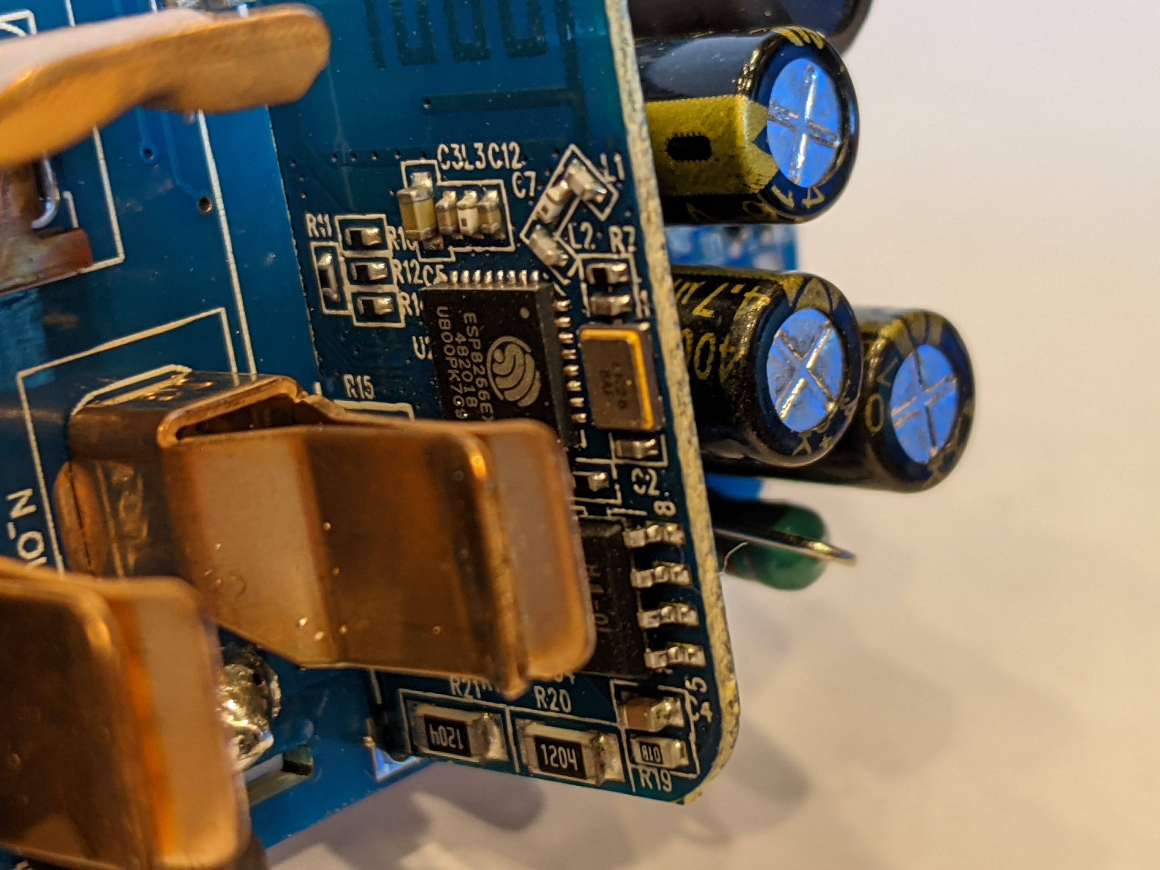
A vertical PCB with the ESP8266 chip:
The left side of the board:

The right side of the board:

The back side of the vertical PCB with the 1MB flash chip:

A few close-ups of the vertical PCB:


A picture of the interior of the case:

An annotated view of the bottom of the circuit board:

Here I’ve blacked the area of the case that gives access to the programming portion of the mainboard:

With a programming USB serial port attached:
