


Available from:
Amazon.de
Amazon.com
| GPIO # | Component |
|---|---|
| GPIO00 | None |
| GPIO01 | Tuya Tx |
| GPIO02 | None |
| GPIO03 | Tuya Rx |
| GPIO04 | None |
| GPIO05 | None |
| GPIO09 | None |
| GPIO10 | None |
| GPIO12 | None |
| GPIO13 | None |
| GPIO14 | None |
| GPIO15 | None |
| GPIO16 | None |
| GPIO17 | None |
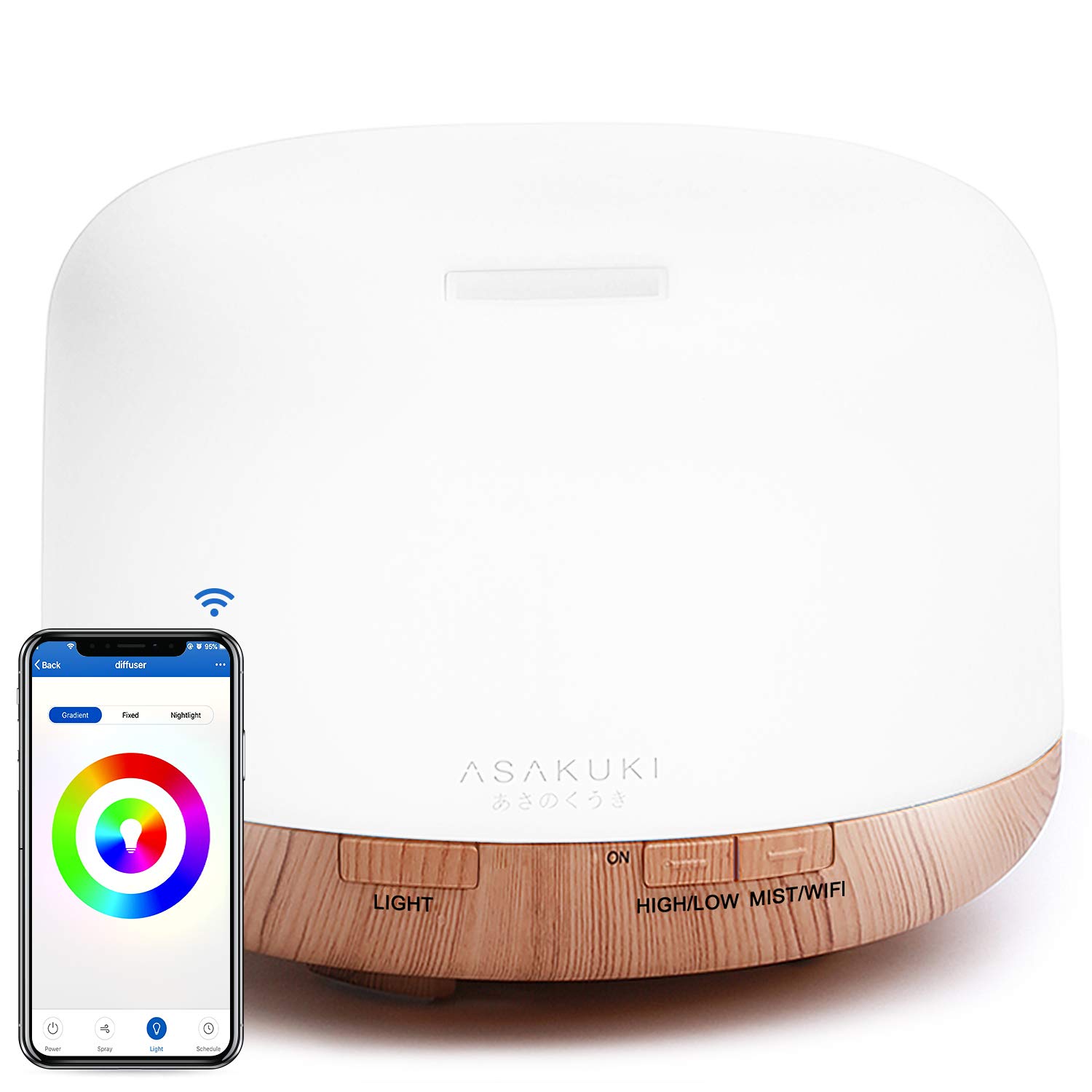
{"NAME":"Asakuki","GPIO":[0,2272,0,2304,0,0,0,0,0,0,0,0,0,0],"FLAG":0,"BASE":54,"CMND":"TuyaMCU 11,1 | TuyaMCU 12,11 | TuyaMCU 21,111 | TuyaMCU 24,108 | TuyaMCU 61,103 | TuyaMCU 62,110"}NOTE from KJ7PPK on 5/10/2026: Ordered and received this diffuser via Amazon, is now using WBR3 which to my understanding would need to be replaced with another chip to convert from Tuya. :(
##
Flashing
Flashing via Tuya-Convert (OTA) seems to be no longer possible due to the PSK key issue.
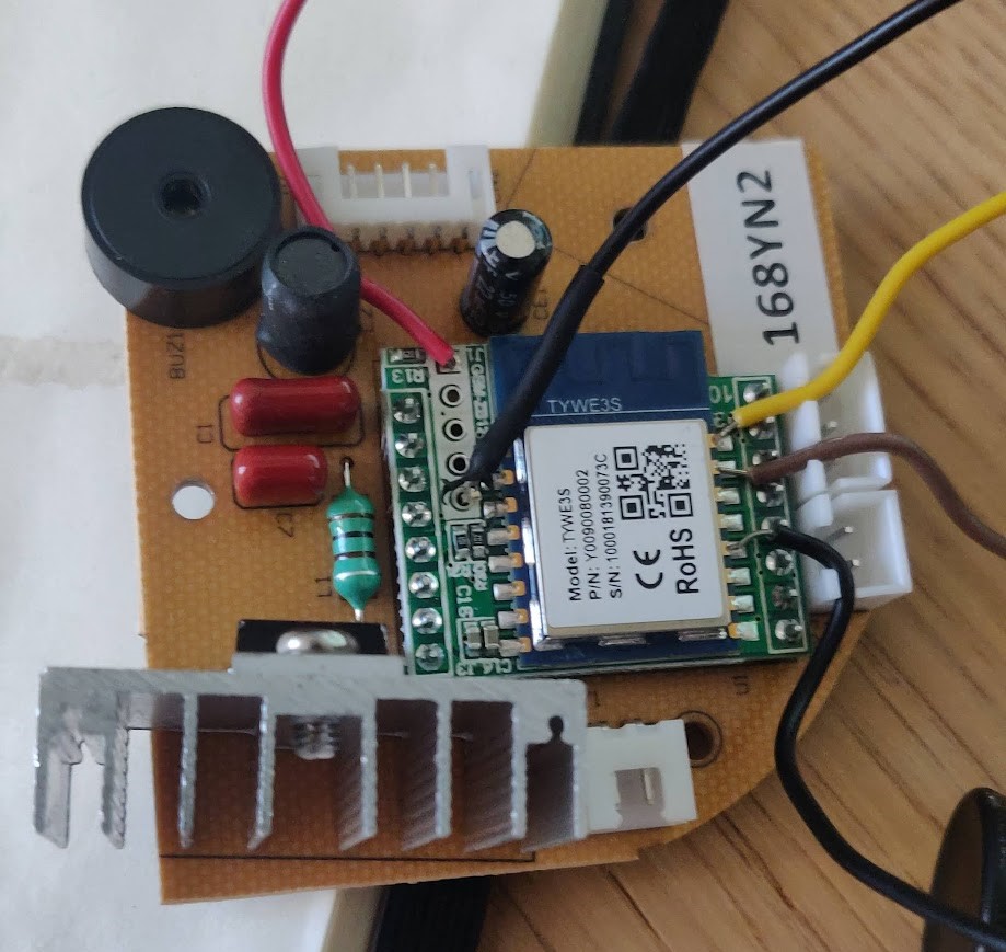
Serial flashing can be done relatively easy without soldering. First, have a look at this guide. The device has a TYWE3S module with a MCU. The TYWE3S mostly takes care of Wi-Fi and software features while the MCU controls the actual hardware (buttons, lights, etc.). The MCU is interfaced to TYWE3S using the serial interface which connects to the Rx and Tx pins.
To flash Tasmota, just disassemble the unit (6 screws), remove the connectors and use some wire to connect TX, RX, GPIO0 and RST directly in the TYWE3S. As you can see in the image, there are headers for VCC and GND in the board. Make sure to ground GPIO0 during boot. To avoid interferences from the MCU, bridge RST to GND on the MCU too.
Functions
dpID 1 device power: 0 = off / 1 = on
dpID 11 light power: 0 = off / 1 = on
dpID 12 error notification: 0 = ok / 1 = error
dpID 13 countdown mode options: 0 = off / 1 = 1hr / 2 = 3hr not needed in Tasmota, use Timer feature instead
dpID 14 countdown status: reports value of 0…360 minutes not needed with Tasmota, use Timer feature instead
dpID 103 mist strength: 0 = low / 1 = high
dpID 108 light color: 14 char value in hex (set with TuyaRGB 3)
dpID 110 light mode: 0 = rgb_cycle / 1 = color / 2 = white
dpID 111 light dimmer
Configuration
After applying the template and configuring Wi-Fi and MQTT, issue the following commands:
Backlog TuyaMCU 11,1; TuyaMCU 12,11; TuyaMCU 21,111; TuyaMCU 24,108; TuyaMCU 61,103; TuyaMCU 62,110
This will:
- map tasmota relay1 with dpID 1 (diffuser on/off)
- map tasmota relay2 with dpID 11 (light on/off)
- map tasmota dimmer with dpID 111 (dimmer)
- map tasmota enum1 with dpID 103 (mist strength)
- map tasmota enum2 with dpID 110 (light mode)
After a restart issue the rest of configurations:
Backlog TuyaRGB 3; DimmerRange 0,255; TuyaEnumList 1,1; TuyaEnumList 2,2; SetOption17
This will:
- define the RGB Hex format used by the MCU
- declare the dimmer range from 0 to 255
- declare the enum1 and enum2 range
- show color in messages as a comma-separated decimal string
Now we will create a few rules. First rule is used to prevent the device going into countdown mode (f.e. using on device controls) and complete MCU status update on restart.
Rule1 on tuyareceived#dptype4id13!=0 do tuyasend4 13,0 endon on scheme#data!=0 do backlog0 scheme 0; tuyaenum2 0 endon
Second rule sends two new MQTT topics: an error topic in case of the device is running out of water and a fanmode topic the mist strength
Rule2 on tuyareceived#dptype5id12 do publish stat/%topic%/error %value% endon on tuyareceived#dptype4id103==1 do publish stat/%topic%/fanmode high endon on tuyareceived#dptype4id103==0 do publish stat/%topic%/fanmode low endon
Third rule will shut down the light after turning on the difusser.
Rule3 on Power1#state=1 do Backlog delay 5; tuyaenum2 1; tuyasend1 11,0 endon on Power2#state=0 do tuyaenum2 1 endon
Finally enable the rules:
rule0 1
Label webUI buttons and set friendly names for power outputs:
Backlog WebButton1 Diffuser; WebButton2 Light; FriendlyName1 Diffuser Fan; FriendlyName2 Diffuser Light
What you get
Power1turns the diffuser on or off in stored mist strength mode as device power statusPower2controls the light as an RGB LightTuyaEnum1is for mist strength status and control:0for low /1for highTuyaEnum2is for light mode status and control:0for RGB cycle /1for solid color /2for solid white
Long press on device’s power button initiates Tasmota’s Wi-Fi config.
Home Assistant configuration
Home Assistant sends a command_topic every time a color/brightness parameter of a light is changed. This makes the diffuser to start a RGB cycle, losing the color/brightness selected. To avoid this, I have created an automation to skip sending the power on command in case the light is already turned on. A similar approach has been used to change the payload of the effect_command_topic.
fan:
  - platform: mqtt
    name: "Difusor"
    unique_id: "difusor"
    state_topic: "stat/difusor/RESULT"
    state_value_template: "{% if value_json.POWER1 is defined %}{{ value_json.POWER1 }}{% endif%}"
    command_topic: "cmnd/difusor/POWER1"
    preset_modes:
    -  "high"
    -  "low"
    preset_mode_state_topic: "stat/difusor/fanmode"
    preset_mode_command_topic: "cmnd/difusor/tuyaenum1"
    preset_mode_command_template: '{{ 1 if value == "high" else 0 }}'
    availability_topic: "tele/difusor/LWT"
    payload_available: "Online"
    payload_not_available: "Offline"

binary_sensor:
  - platform: mqtt
    name: "Error difusor"
    unique_id: "error_difusor"
    state_topic: "stat/difusor/error"
    value_template: "{{ 'ON' if value != '0X00' else 'OFF' }}"
    device_class: problem
    availability_topic: "tele/difusor/LWT"
    payload_available: "Online"
    payload_not_available: "Offline"

light:
  - platform: mqtt
    name: "Lámpara del difusor"
    unique_id: "luz_difusor"
    availability_topic: "tele/difusor/LWT"
    payload_available: "Online"
    payload_not_available: "Offline"
    command_topic: "cmnd/difusor/POWER2GW"
    state_topic: "stat/difusor/RESULT"
    state_value_template: "{% if value_json.POWER2 is defined %}{{ value_json.POWER2 }}{% endif %}"
    payload_on: "ON"
    payload_off: "OFF"
    rgb_command_topic: "cmnd/difusor/tuyasend3"
    rgb_command_template: "{% set brightness = state_attr('light.luz_difusor','brightness') | int %}{{ '108,%02x%02x%02x646464' | format(red, green, blue)}}{{ '%02x' | format(brightness) }}"
    rgb_value_template: "{% if value_json.POWER2 is defined and value_json.POWER2 == 'ON' %}{{value_json.Color.split(',')[0:3]|join(',')}}{% endif %}"
    rgb_state_topic: "stat/difusor/RESULT"
    brightness_command_topic: "cmnd/difusor/Dimmer"
    brightness_state_topic: "stat/difusor/RESULT"
    brightness_scale: 100
    brightness_value_template: "{% if value_json.POWER2 is defined and value_json.POWER2 == 'ON' %}{{value_json.Dimmer}}{% endif %}"
    effect_list:
    - "Ciclo"
    - "Fijo"
    effect_command_topic: "cmnd/difusor/tuyaenum2GW"
    effect_state_topic : "stat/difusor/RESULT"
    effect_value_template : "{% if value_json.TuyaEnum2 is defined and value_json.TuyaEnum2 == 0 %}{{'Ciclo'}}{% elif value_json.TuyaEnum2 is defined and value_json.TuyaEnum2 is defined and value_json.TuyaEnum2 == 1 %}{{'No'}}{% endif %}"

automation:
  - alias: "Difusor Reenvío MQTT1"
    id: difusor_reenvio_mqtt1
    trigger:
      - platform: mqtt
        topic: 'cmnd/difusor/POWER2GW'
    condition:
      condition: template
      value_template: "{{ trigger.payload | lower != states('light.luz_difusor') }}"
    action:
      - service: mqtt.publish
        data_template:
          topic: 'cmnd/difusor/POWER2'
          payload: "{{ trigger.payload }}"

  - alias: "Difusor Reenvío MQTT2"
    id: difusor_reenvio_mqtt2
    trigger:
      - platform: mqtt
        topic: 'cmnd/difusor/tuyaenum2GW'
    action:
      - service: mqtt.publish
        data_template:
          topic: 'cmnd/difusor/tuyaenum2'
          payload_template: >
            {% if 'Ciclo' in trigger.payload -%}
              {{ 0 }}
            {%- elif 'Fijo' in trigger.payload -%}
              {{ 1 }}
            {%- else -%}
              {{ 2 }}
            {%- endif %}

Pinout
 .
.