


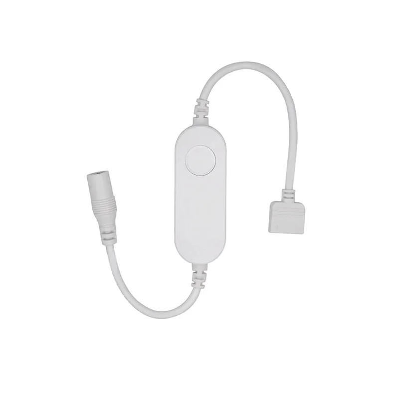
Available from:
Aliexpress.com
Manufacturer:
Athom.tech
Install method:
Tasmota pre-installed
| GPIO # | Component |
|---|---|
| GPIO00 | Button 1 |
| GPIO01 | None |
| GPIO02 | None |
| GPIO03 | None |
| GPIO04 | PWM 2 |
| GPIO05 | None |
| GPIO09 | None |
| GPIO10 | None |
| GPIO12 | PWM 1 |
| GPIO13 | None |
| GPIO14 | PWM 3 |
| GPIO15 | None |
| GPIO16 | None |
| GPIO17 | None |
{"NAME":"LS5050C-TAS","GPIO":[32,0,0,0,417,0,0,0,416,0,418,0,0,0],"FLAG":0,"BASE":18}
This device supports 3 PWM channels, but can easily be modified to support 4, to control RGBW LEDs: The back of the case is held in place by clips, and prises open. In order to enable the fourth channel, you need to add three components: ‘0805’ size surface-mount resistors of values 1k and 10k, and a ‘SOT-23’ size surface-mount N-channel MOSFET type AO3400 (marked A09T), in the positions shown. You will also want to replace the output cable with one with 5 conductors.
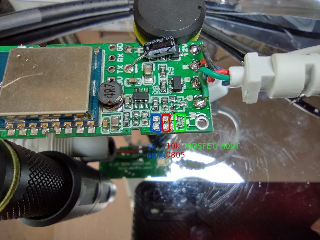
To enable the extra channel (which is connected to GPIO13) in Tasmota, you can use the following template:
’{“NAME”:”LS5050C-TAS”,”GPIO”:[32,0,0,0,416,0,0,0,417,419,418,0,0,0],”FLAG”:0,”BASE”:18}’ (Note: This also swaps the order of the first two channels so the colours align with the ‘R’ ‘G’ ‘B’ and ‘W’ markings on the PCB.)