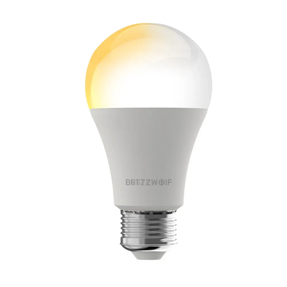
Available from:
Banggood.com
Aliexpress.com
Manufacturer:
Blitzwolf.com
Install method:
USB to Serial
| GPIO # | Component |
|---|---|
| GPIO00 | None |
| GPIO01 | None |
| GPIO02 | None |
| GPIO03 | None |
| GPIO04 | None |
| GPIO05 | None |
| GPIO09 | None |
| GPIO10 | None |
| GPIO12 | None |
| GPIO13 | PWM2i |
| GPIO14 | None |
| GPIO15 | PWM1 |
| GPIO16 | None |
| FLAG | None |
{"NAME":"BW-LT29","GPIO":[0,0,0,0,0,0,0,0,0,47,0,37,0],"FLAG":0,"BASE":18}Use SetOption92 1 after applying template.
Serial Flashing
Tuya-Convert did not work on this bulb due to new hardware. To flash this bulb you’ll need to solder only two wires but they will be tricky.
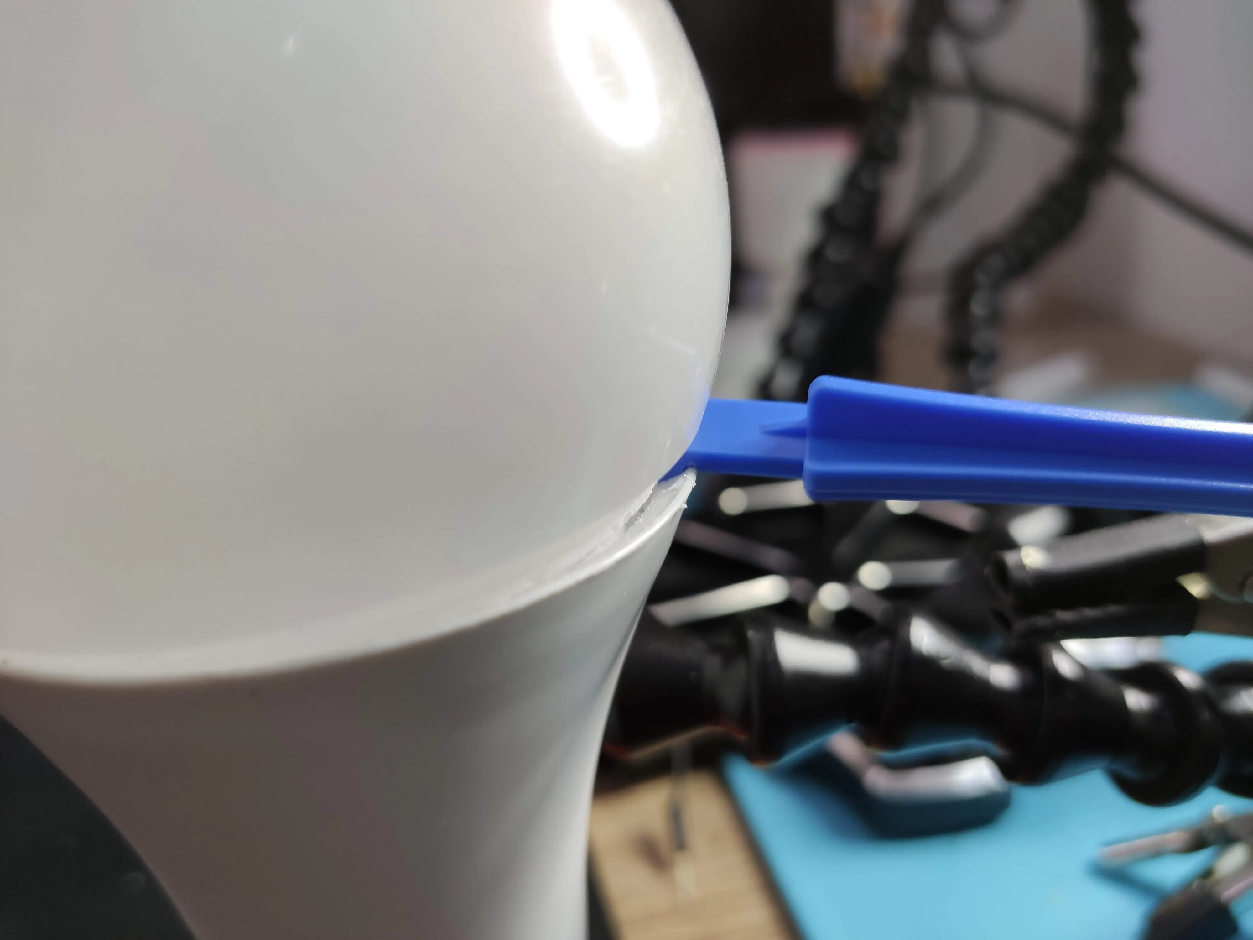
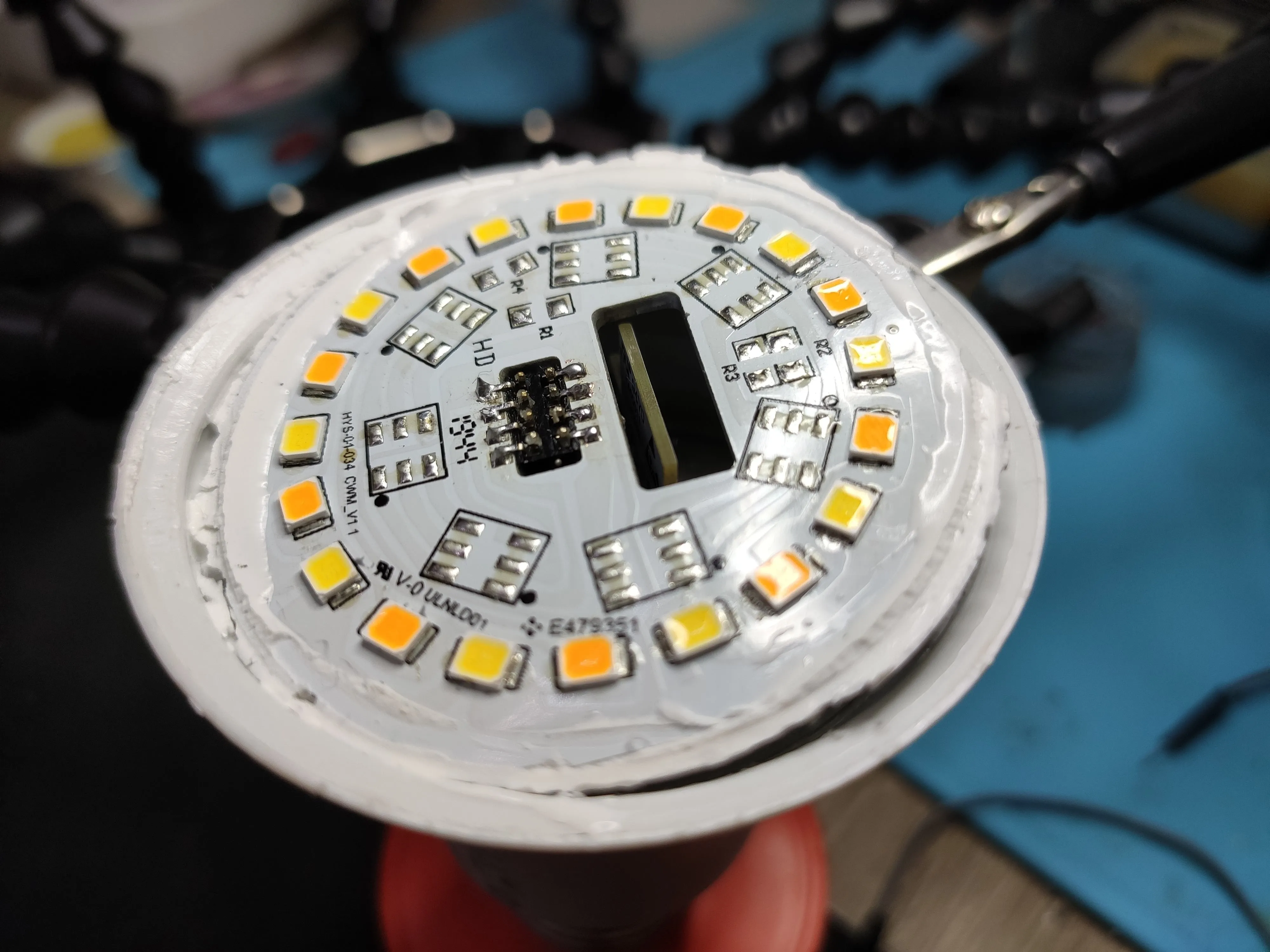
Pop the diffuser dome by using a plastic prying tool to circle around the base which will loosen the glue and make the dome easy to remove.
Lift up the top PCB, it is not screwed on or soldered to the base. The connection is made with the 8 pin head visible.
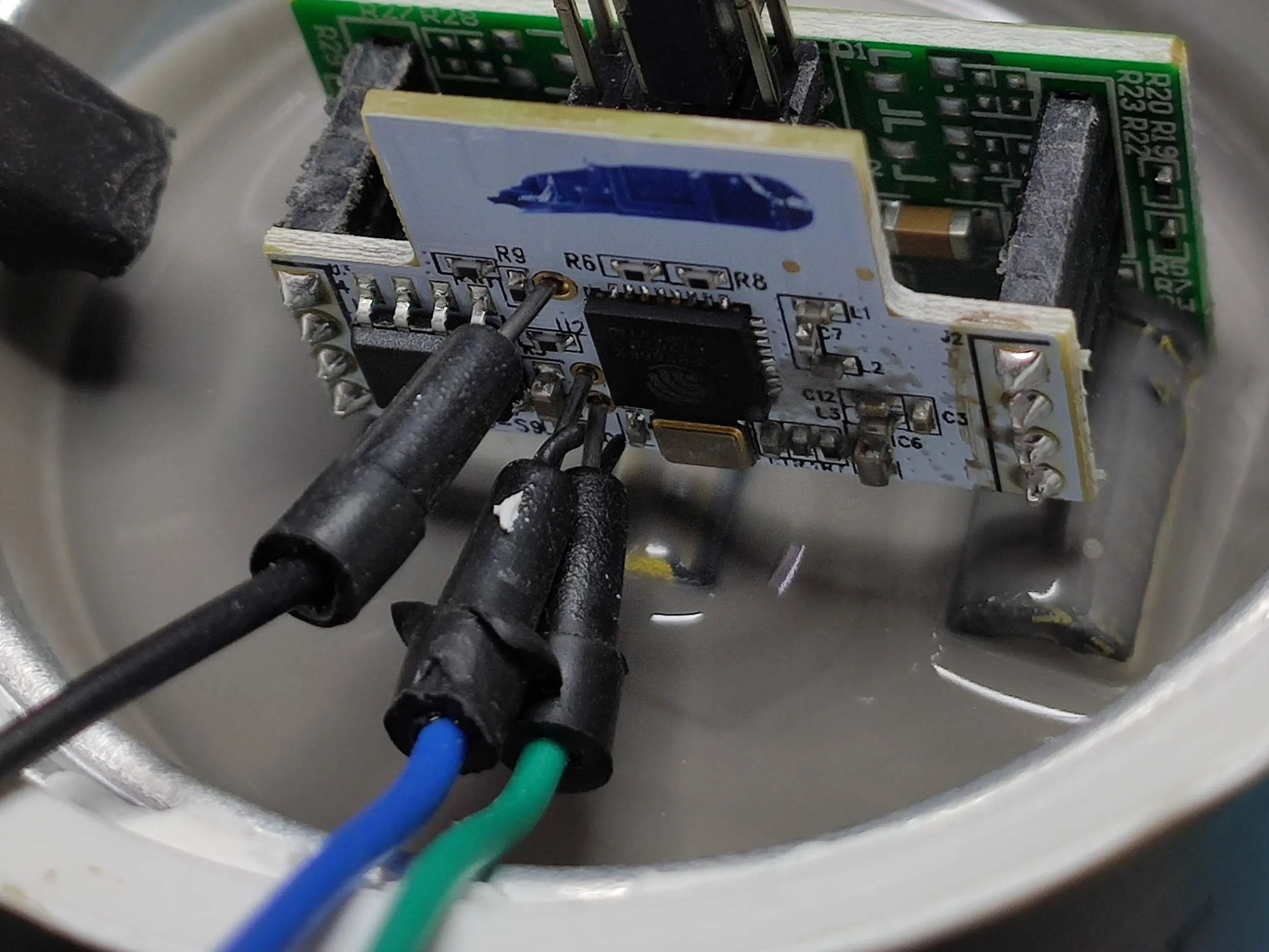
RX, TX and IO0 are nicely labelled on the wifi board and have small pinholes that can fit breadboard jumper cables.
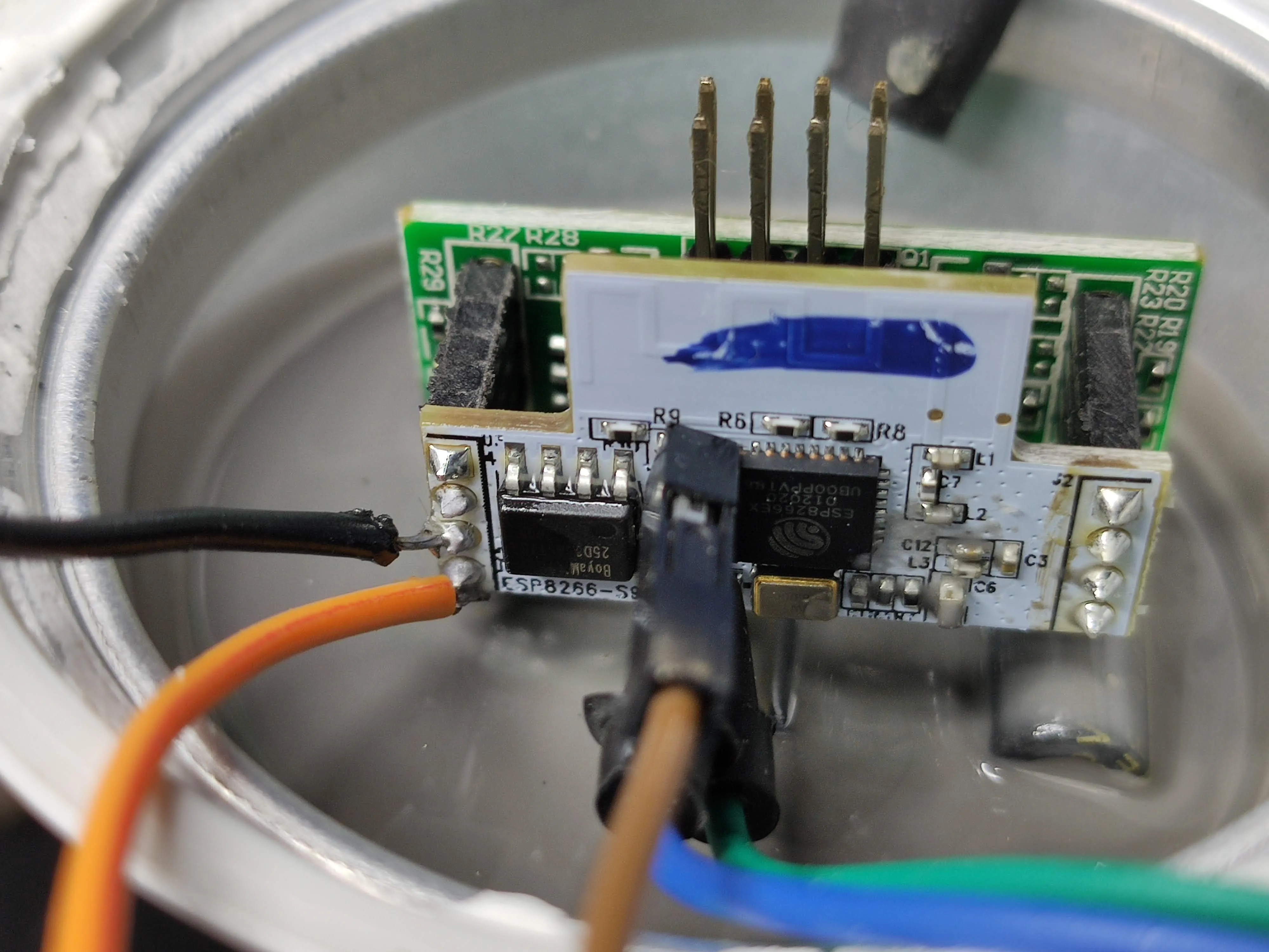
Now comes the tricky part: to get VCC and GND youneed to solder to the wifi board header joints. There is GND and VCC on the green PCB that connect to the 8 pin header but they don’t power the ESP8266 properly. There’s probably some voltage regulation in between but I didn’t examine it further.
All broken out ESP8266 pins are labelled on the other side. In my image VCC is the orange wire and GND the black one.


