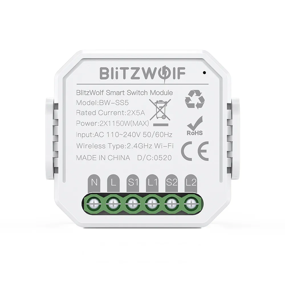
Available from:
Banggood.com
Aliexpress.com
Manufacturer:
Blitzwolf.com
Install method:
USB to Serial
| GPIO # | Component |
|---|---|
| GPIO00 | None |
| GPIO01 | None |
| GPIO02 | Button1 |
| GPIO03 | None |
| GPIO04 | Buzzer |
| GPIO05 | None |
| GPIO09 | None |
| GPIO10 | None |
| GPIO12 | Switch2 |
| GPIO13 | Switch1 |
| GPIO14 | Relay1 |
| GPIO15 | Relay2 |
| GPIO16 | None |
| FLAG | None |
{"NAME":"BlitzWolf SS5 2 Gang","GPIO":[0,0,17,0,160,0,0,0,10,9,21,22,0],"FLAG":0,"BASE":18}This device uses AC frequency detection circuits on switch inputs supported since Tasmota 8.4.
After applying the template enable AC frequency detection feature using ‘SwitchDebounce’ command. ‘SwitchDebounce 69’ is a good place to start, which means 3 pulses (60 milliseconds) to switch on or off. When this feature is enabled, you can use them as regular switches (set ‘SwitchMode’, use in rules and do anything you can do with a regular switch).
The BW-SS5 have AC switch detection circuity with rectified AC guiding the input GPIOs instead of digital high/low. This means the MCU will see a constant stream of pulses for “On” and no or less (long cables do cause inductive coupling, so AC on one wire will cause AC to the other wire as well) for “Off”. Tasmota has a special mode for this, “SwitchDebounce xxx9”, “xxx” being centiseconds (10 ms each) and “9” meaning we want xxx cs long pulse streams or lack of to turn the switch on/off. Most documentation mention “69” as a suitable starting point but I had to increase that to 209 to work properly, thus the command would be “SwitchDebounce 209”.


