


Available from:
Banggood.com
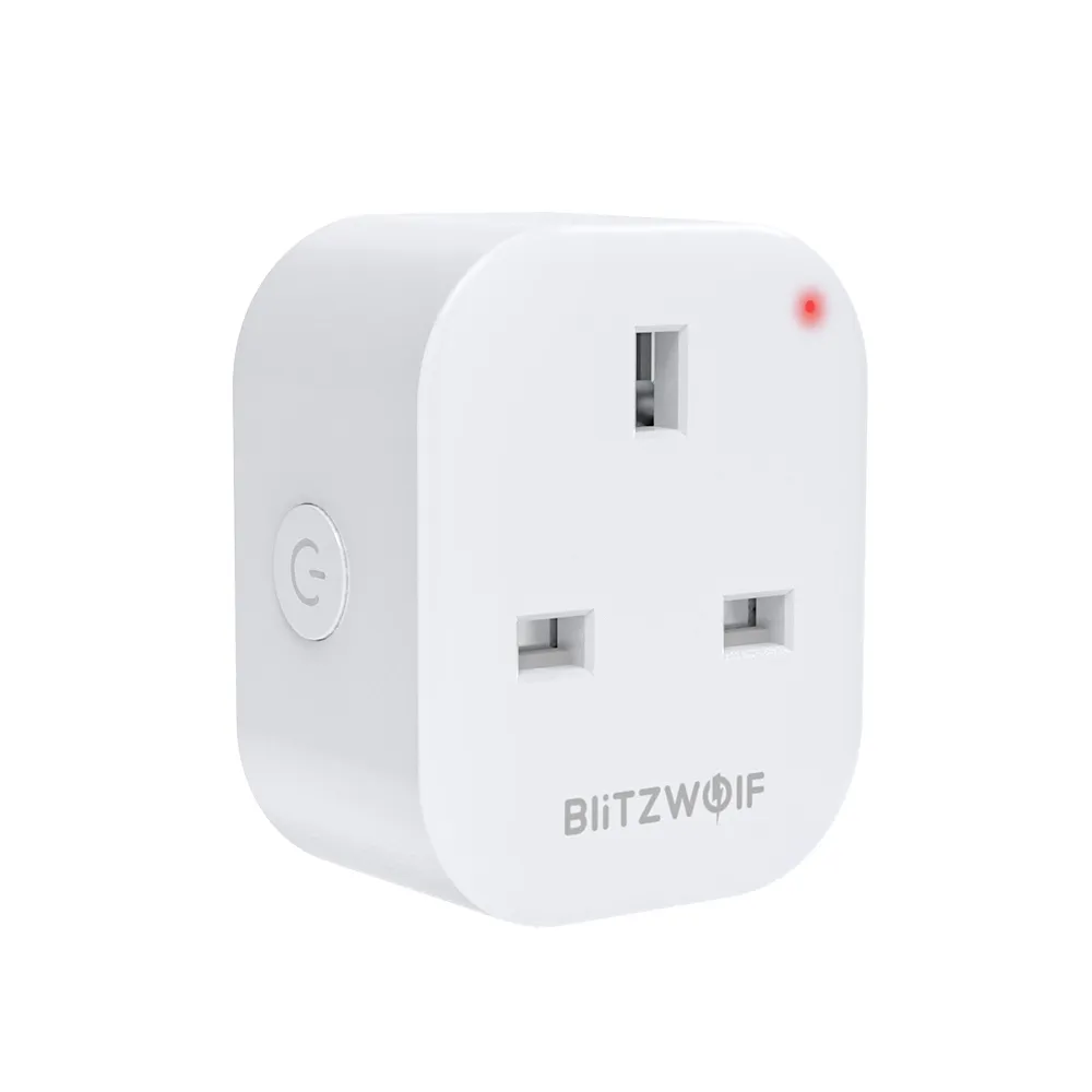
Manufacturer:
Blitzwolf.com
Install method:
USB to Serial
| GPIO # | Component |
|---|---|
| GPIO00 | Led_i 1 |
| GPIO01 | None |
| GPIO02 | None |
| GPIO03 | HLWBL SELi |
| GPIO04 | None |
| GPIO05 | BL0937 CF |
| GPIO09 | None |
| GPIO10 | None |
| GPIO12 | None |
| GPIO13 | Button 1 |
| GPIO14 | HLWBL CF1 |
| GPIO15 | Relay 1 |
| GPIO16 | None |
| GPIO17 | None |
{"NAME":"BlitzWolf-SHP11","GPIO":[320,0,0,2624,0,2720,0,0,0,32,2656,224,0,0],"FLAG":0,"BASE":18}Getting into the SHP-11 is a case of spudgering along the obvious seam: The plastic face from which the mains plug pins emerge is flat and a couple of mm thick, with the main body glued around its edge, so you need to spudge inwards parallel to the pins to break the glue, rather than too much levering outwards (there aren’t any tabs to release, once the glue breaks the case just lifts off). Once you’re in, contacts attached to the live and neutral pins are soldered to the board. These are easy to de-solder with a hot iron (I used 450C). Take care not to touch adjacent plastic components with the soldering iron. Once the case has been removed, the chip is found sticking up in one corner. Flip the board over and with the ground pin hole at the bottom of the board Like So, the pins are as follows:
   +3.3V | GND
RX/GPIO3 | TX/GPIO1
   GPIO4 | GPIO5
   GPIO0 | GPIO2
  GPIO13 | GPIO15
  GPIO14 | GPIO12
     ??? | ???
The pin below GPIO14 causes the unit to crash when probed - possibly a reset line?
The original version of this page described the power pin as 5V. It appears to run (and flash) fine when supplied with 3.3V, so I was reluctant to apply 5V to the pin.
To flash you need to connect RX on the board to TX on your serial adaptor and vice-versa. Connect GPIO0 to GND while programming. After reassembly, the case can be neatly glued shut. I used a hot-melt glue designed for plastics.
There are two LEDs: The blue LED is connected to GPIO0, and lights when LOW The red LED is connected to GPIO15 along with the relay, and lights when HIGH (relay on)
The button is a momentary switch on GPIO13
There is a BL0937 power meter chip, wired as follows:
ESP     BL0937        Tasmota template
GPIO5   CF  (pin 6)   BL0937 CF
GPIO14  CF1 (pin 7)   HLWBL CF1
GPIO3   SEL (pin 8)   HLWBL SEL_i
I found that sensible readings for voltage and current appeared immediately if GPIO3 was left unset. I set SerialLog to 0 and restarted to avoid conflicting with GPIO3. Once “HLWBL SEL_i” is defined, current and reactive power displays are enabled, and something funny seems to happen with the calibration process. I went round in circles several times, but was eventually able to achieve sensible values by tweaking VoltageCal, PowerCal and CurrentCal manually, rather than using PowerSet, VoltageSet etc.