


Available from:
Amazon.com
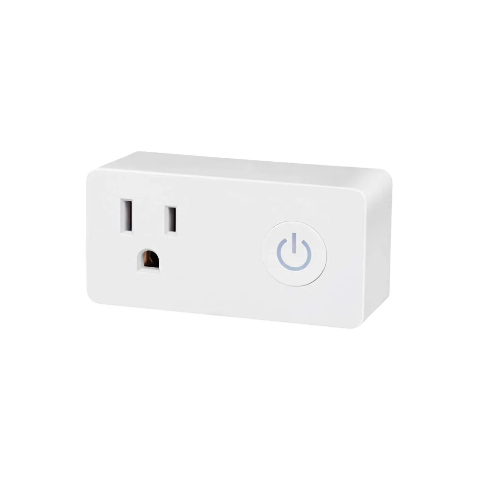
Install method:
Replace module
| GPIO # | Component |
|---|---|
| GPIO00 | None |
| GPIO01 | Led1 |
| GPIO02 | None |
| GPIO03 | Button1 |
| GPIO04 | BL0937 CF |
| GPIO05 | HLWBL CF1 |
| GPIO09 | None |
| GPIO10 | None |
| GPIO12 | HLWBL SELi |
| GPIO13 | Led2 |
| GPIO14 | Relay1 |
| GPIO15 | None |
| GPIO16 | None |
| FLAG | None |
{"NAME":"BNC-60/U133TJ","GPIO":[0,52,0,17,134,132,0,0,131,53,21,0,0],"FLAG":0,"BASE":18}This device uses WB2S module which needs to be replaced with ESP-02S, WT-01N or WT32C3-01N. Besides the module, this process will require a heat gun, soldering tools and moderate soldering skill.
The orginal template had GPIO1 as Led1i (56) and GPIO13 as Led2i (57) for Template parameters. Those parameters result in the power button glowing red color all the time. Using the non-inverse Led parameters Led1 (52) and Led2 (53) result in the power button glowing blue when on and purple when off.
Firmware flashing has to be accomplished via the usual manual methods where one has to first partially dismantle the device. The plastic shell is glued but it does cleanly open with careful utility knifing. Unlike some plug devices the plastic shell back plate is molded to the mains prongs (US version). There is a dogleg in the neutral and hot prongs that is captured by the plastic back plate. The PCB board must therefore be desoldered from the mains plug prongs for removing the board to have access to its underside where the flashing wiring can be temporarily soldered to the TYWE2S edge solder points. Grounding GPIO0 to put the TYWE2S into flash mode is accomplished by grounding the TYWE2S test pad IO0. The TYWE2S board is mounted to the main pcb board so that the side having the test pads faces inside towards other components. Thus access to test pad IO0 is quite awkward.
NOTE: Device purchased in November 2020 required connecting TX-TX and RX-RX. Worth a shot if your espTool or Tasmotizer is timing out waiting for the device when you’re doing TX-RX & RX-TX like normal.
4-pack device purchased 2nd week of December 2020 from Amazon US now uses WBS2 daughterboard and not compatible with Tasmota. 4-pack ordered 11/29/2020 directly from bn-link.com use WBS2 daughterboard (still have the FCC 2ANDL-TYWE2S on the label):-( So, I guess, these plugs are out:-(
I had the same problem with the W2BS chip and I bought the WT-01N chip, which is an exact replacement, I programmed it with tasmota and installed it, it worked perfectly.
Here is the newer template with a WT32C3-01N:
{"NAME":"BNC-60/U133TJ (ESP32C3)","GPIO":[1,1,1,2656,256,2624,321,1,1,1,2720,0,0,0,0,0,0,0,1,1,64,320],"FLAG":0,"BASE":1}