


Available from:
Banggood.com
Aliexpress.com
Install method:
Tuya-Convert
| GPIO # | Component |
|---|---|
| GPIO00 | None |
| GPIO01 | Tuya Tx |
| GPIO02 | None |
| GPIO03 | Tuya Rx |
| GPIO04 | None |
| GPIO05 | None |
| GPIO09 | None |
| GPIO10 | None |
| GPIO12 | None |
| GPIO13 | None |
| GPIO14 | None |
| GPIO15 | None |
| GPIO16 | None |
| FLAG | None |
{"NAME":"Digoo ZXD21","GPIO":[0,107,0,108,0,0,0,0,0,0,0,0,0],"FLAG":0,"BASE":54}Tuya-Convert might not be possible for this device since the template was added (2020-03-28).

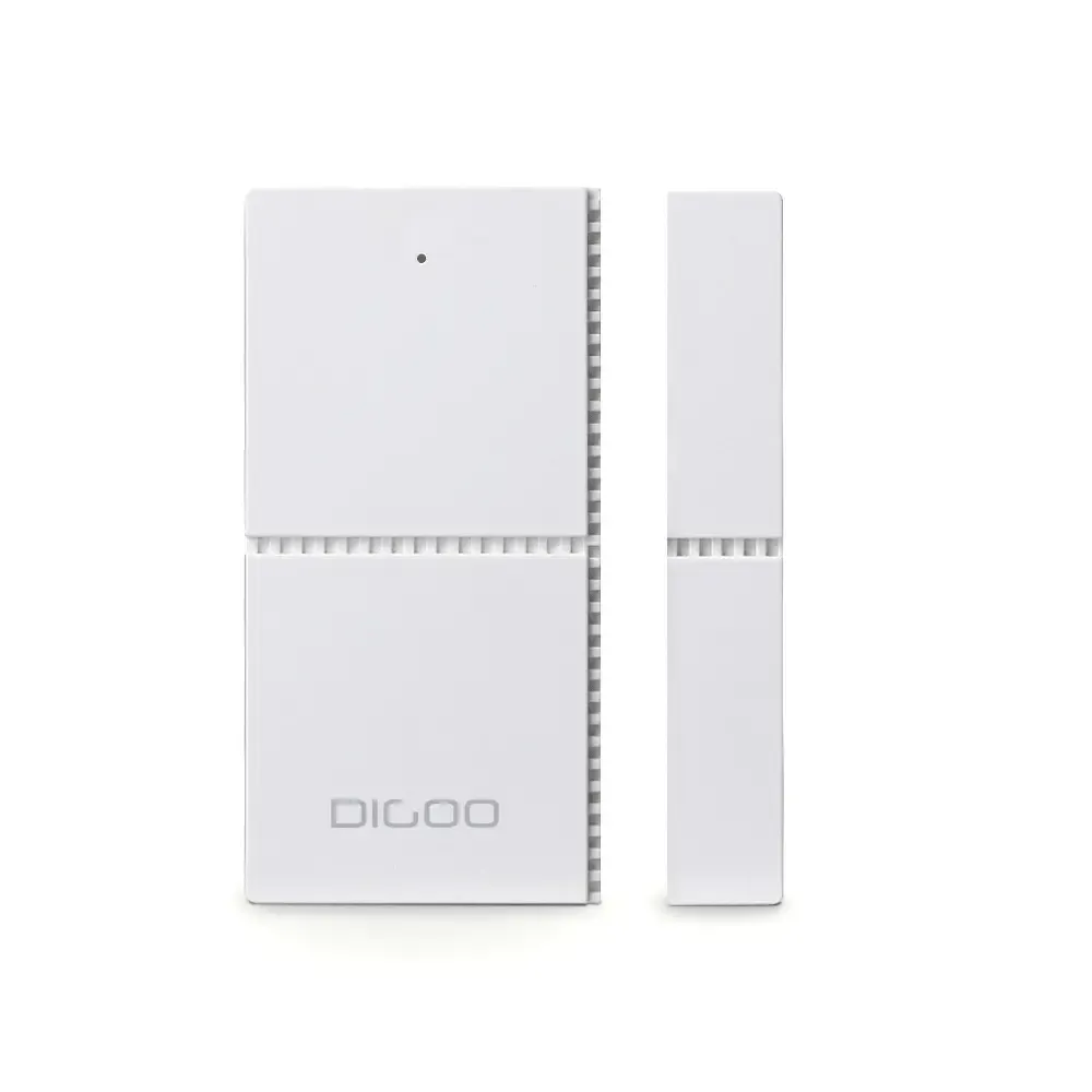
This is a Tuya/Smart Life battery powered contact (door or window) sensor. Runs on two AAA batteries (not supplied with the device).
Identified with MCU Product ID: {"p":"zhnheicnjh6civjf","v":"1.0.0"}.
Flashing
To have best results with this type of device I strongly recommend compiling a stripped down binary. There’s an unofficial binary, compiled from current development release. Flash at your own risk.
Example user_config_override defines (for Tasmota 8.2+).
Tuya-Convert
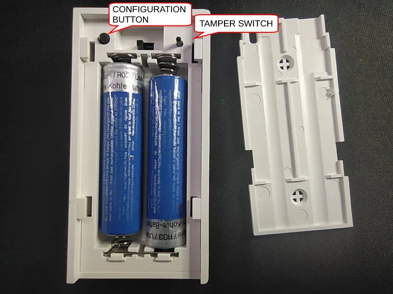
It is possible to flash the device using Tuya-Convert but it might need a couple tries due to the MCU resetting the battery powered TYWE3S module. Prepare everything for Tuya-Convert then long press the configuration button to put the device in pairing mode. Be very quick about issuing commands. If it fails try again, you can continue from some points of the conversion process.
Serial
Easily disassembled by removing the back plate, then prying away the battery holder from the main enclosure.
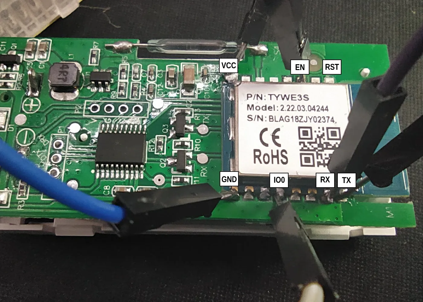
The PCB has only the “V1.2” marking on it and a prominent TYWE3S module with “Model: 2.22.03.04244”. There are broken out pins for 3v3, RX, TX and GND but to be able to solder a pin header in them you need to desolder the battery holder which is probably not worth the trouble since all the needed pins are accessible on the TYWE3S module.
To be able to flash this module you will need to connect:
| TYWE3S | serial-to-USB |
| TX | RX |
| RX | TX |
| GND | GND |
| GPIO0 | GND |
| VCC | 3V3 |
| EN | 3V3 |
| RST | 3V3 |
RST is supposed to be pulled high only on boot but in my case it had to be connected throughout the entire flash process.
Configuration
Please read TuyaMCU article to understand the terminology and configuration process.
To make the configuration process easier you can use the Configuration button to prevent the ZXD21 from turning off for 30 seconds.
Change device to a TuyaMCU module using Module 54 command (or apply the provided template, result is the same)
Disable multipress button options to prevent a device reset or Wi-Fi AP config mode, disable Power Cycle recovery, turn on TuyaReceived publish to MQTT and set switchmode to follow instead of toggle.
Backlog SetOption1 1; SetOption65 1; SetOption66 1; SwitchMode 1
Switch the device to battery powered sensor mode (fnId 51):
TuyaMCU 51,21
Once you do this the device will stay powered on for only 10 seconds. If you want to do other configurations or upgrade firmware first you have to turn battery sensor mode using TuyaMCU 51,0, turn it back on when you’re finished.
Check with TuyaMCU for the following configuration:
{"TuyaMCU":[{"fnId":11,"dpId":1},{"fnId":51,"dpId":21}]}
Functions
dpID 1 reed switch: closed = off / open = on
dpID 2 battery percentage
dpID 3 tamper alarm
This devices uses a different command word (Cmnd =5 ) in its messaging so battery percentage and tamper alarm cannot be interpreted by the TuyaMCU driver.
Reed Switch
dpID 1 is assigned to Relay1 by default. It will report status using POWER topic.
Tamper Switch
When tamper switch is depressed it wakes up Tasmota and sends the following:
{"TuyaReceived":{"Data":"55AA00050005030400010112","Cmnd":5,"CmndData":"0304000101"}} or {"TuyaReceived":{"Data":"55AA00050005030400010213","Cmnd":5,"CmndData":"0304000102"}}
You can use this rule to report to an MQTT topic when the tamper switch is triggered.
Rule1 ON TuyaReceived#Data=55AA00050005030400010112 DO Publish %topic%/TAMPER ON ENDON ON TuyaReceived#Data=55AA00050005030400010213 DO Publish %topic%/TAMPER ON ENDON
Don’t forget to turn on the rule with Rule1 1!
Battery Percentage
Battery percentage is posted in a message similar to
{"TuyaReceived":{"Data":"55AA00050008020200040000004256","Cmnd":5,"CmndData":"0202000400000042"}.
In this case the CmndData string is longer from other dpID’s (16 characters long). Last two digits are battery percentage in hexadecimal. There’s no easy way to read battery status in Tasmota.
Battery percentage sensor in Home Assistant:
- platform: mqtt
  name: "Digoo Battery"
  unit_of_measurement: '%'
  state_topic: "tele/digoo/RESULT"
  value_template: >
    {% set test = value_json['TuyaReceived'].CmndData | length %}
    {% if value_json.TuyaReceived is defined and value_json['TuyaReceived'].Cmnd == 5 and test == 16 %}
    {{ value_json['TuyaReceived'].CmndData[14:16]|int(base=16) }}
    {% else %}
    {{ states('sensor.digoo_battery') }}
    {% endif %}
  device_class: battery
Final Notes
There is a significant delay (~4s on my network with the latest stripped down binary and a static IP) between reed actuation and first MQTT message so I don’t recommmend this in critical spots where a fast response is required.
If the batteries are weak sensor might be stuck in a bootloop or spawn an ESP-XXXXX AP. The bootloop can reset Tasmota to “factory defaults”. You can disable bootloop protection with SetOption36 0 but that might also put the sensor in a permanent bootloop until the battery dies.
Due too all the possibilites of resets and configuration corruptions a custom binary with all important information precompiled is the best solution.