


Available from:
Aliexpress.com
Banggood.com
Manomano.de
Install method:
USB to Serial
| GPIO # | Component |
|---|---|
| GPIO00 | User |
| GPIO01 | Tuya Tx |
| GPIO02 | User |
| GPIO03 | Tuya Rx |
| GPIO04 | User |
| GPIO05 | User |
| GPIO09 | None |
| GPIO10 | None |
| GPIO12 | User |
| GPIO13 | User |
| GPIO14 | User |
| GPIO15 | User |
| GPIO16 | User |
| GPIO17 | None |
{"NAME":"DG-ZXGS21","GPIO":[1,2272,1,2304,1,1,0,0,1,1,1,1,1,0],"FLAG":0,"BASE":54}
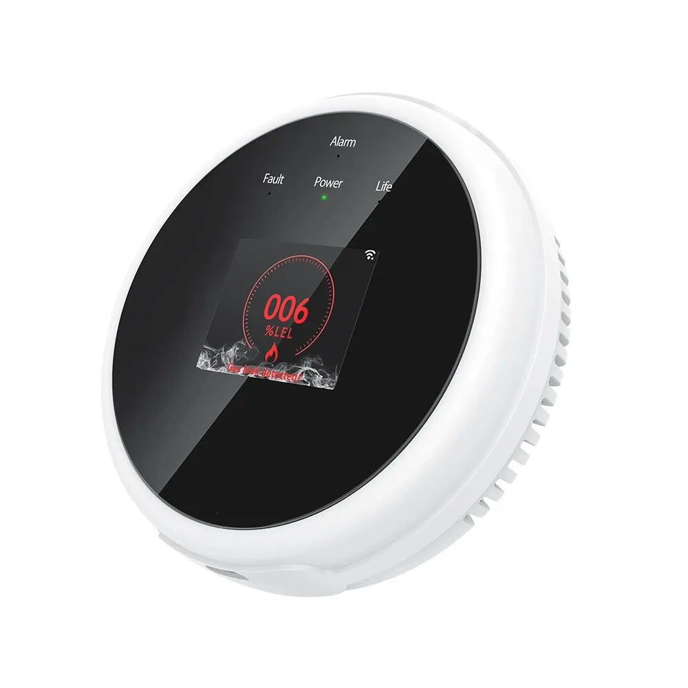
This is a Tuya gas and heat detector and alarm with a clock and info LCD display. It has a TYWE3S module and a GD32E230C8T6 STM32 compatible MCU.
Identified with MCU Product ID: {"p":"ozcdjaqrxauonq1f","v":"1.0.0","m":2}.
Flashing
Grip the backside clips with pliers from the outer rim and slowly release all 4 of them in order.
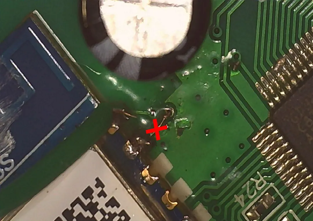
I did not manage to find a way to disable the MCU so you have to cut the RX pin PCB trace to flash the Wi-Fi module.
I would recommend not connecting 3v3 to your serial-to-USB adapter but power the device using its USB port.
Connect the required TX, RX and GND pins according to the TYWE3S pinout and ground GPIO0 during boot.
After flashing solder back the RX line to reestablish communication with the MCU.
Functions
Sensor uses the built in speaker as an alarm and to play voice prompts and sound the alarm:
The speaker and LED’s are controlled by the MCU and there is no way to control them with Tasmota.
When the sensor it first powered on it will be in preheat mode.
dpID 1 gas: 0 = detected gas / 1 = no gas
dpID 2 gas amount = displayed %LEL value
dpID 7 alarm volume: 0 = mute, 1 = on
dpID 8 test function trigger
dpID 9 test result: 0 = checking, 1 = check success, 2 = check_failure, 3 = other
dpID 10 preheat state: 0 = normal operation, 1 = sensor preheating mode
dpID 11 error state: fault, serious_fault, sensor_fault, probe_fault, power_fault
dpID 12 lifecycle indicator: 0 = end of life, 1 = operational
dpID 16 silence alarm: 0 = nothing, 1 = silences currently playing alarm
dpID 18 heat alarm state (0 = alarm, 1 = normal)
dpID 19 temperature value
dpID 101 set heat alarm threshold
dpID 102 set language: 0 = chinese, 1 = english
Configuration
Please read TuyaMCU article to understand the terminology and configuration process.
Change device to a TuyaMCU module (or apply the provided template, result is the same)
Module 54
Set the following configuration:
Backlog TuyaMCU 79,2; TuyaMCU 71,19; TuyaMCU 72,101; TuyaMCU 11,16; TuyaMCU 12,8; TuyaMCU 61,102;
To properly update displayed time and date and use fnID 79 you need Tasmota v9.3.1.2+.
Backlog TempRes 0; TuyaEnumList 1,1; WebButton1 Mute; WebButton2 Run Test
POWER1 will turn on on either alarm, you can turn it if to mute the sound when alarm is active. It will default to OFF after a few seconds in normal working mode.
POWER2 is used to trigger the built in test.
Gas and heat alarm activations need to be reported to a new topic. A rule example:
rule1 ON tuyareceived#dptype4id1 DO publish stat/%topic%/GAS %value% ENDON ON tuyareceived#dptype4id18 DO publish stat/%topic%/HEAT %value% ENDON
0 reported on either topic means alarm has been activated.
Gas concentration value is sent on dpId2 and reported as a gas sensor. Make sure to use Tasmota v9.3.1.2+ which supports fnID 79 for the gas sensor.
Temperature is reported to dpID 19 with the value in C. You need to set TempOffset 0 to display it correctly in Tasmota.
Use Tuyasend2 101,<value> to adjust threshold temperature which is shown as Set Temperature sensor.
Sometimes the device reverts to Chinese audio. To keep it always English use
backlog rule3 on tuyareceived#DpType4Id102=0 do tuyasend4 102,1 endon; rule3 1