


Available from:
Nl.aliexpress.com
Manufacturer:
Dingtian-tech.com
Install method:
USB to Serial
| GPIO # | Component |
|---|---|
| GPIO00 | ETH POWER |
| GPIO01 | ModBr Tx |
| GPIO02 | Relay 2 |
| GPIO03 | ModBr Rx |
| GPIO04 | None |
| GPIO05 | None |
| GPIO09 | None |
| GPIO10 | None |
| GPIO12 | None |
| GPIO13 | ModBr Tx Ena |
| GPIO14 | None |
| GPIO15 | None |
| GPIO16 | Relay 1 |
| GPIO17 | None |
| GPIO18 | ETH MDIO |
| GPIO19 | None |
| GPIO20 | None |
| GPIO21 | None |
| GPIO22 | None |
| GPIO23 | ETH MDC |
| GPIO24 | None |
| GPIO25 | None |
| GPIO26 | None |
| GPIO27 | None |
| GPIO6 | None |
| GPIO7 | None |
| GPIO8 | None |
| GPIO11 | None |
| GPIO32 | LedLinki |
| GPIO33 | None |
| GPIO34 | None |
| GPIO35 | None |
| GPIO36 | Switch 1 |
| GPIO37 | None |
| GPIO38 | None |
| GPIO39 | Switch 2 |
{"NAME":"Dingtian DT-R002","GPIO":[5536,9408,225,9440,0,0,0,0,0,9952,0,0,224,0,5600,0,0,0,0,5568,0,0,0,0,0,0,0,0,576,0,0,0,160,0,0,161],"FLAG":0,"BASE":1}Warning
When ordering this board ask for relay board with test firmware, otherwise the ESP32 will be locked.
Relay 1 is connected to GPIO 16 which is used for PSRAM in Tasmota, to prevent a pulse on Relay 1 upon boot use the tasmota32-nopsram firmware (https://github.com/arendst/Tasmota/discussions/21266), or use “#define DISABLE_PSRAMCHECK true” in user_config_override.h upon building.
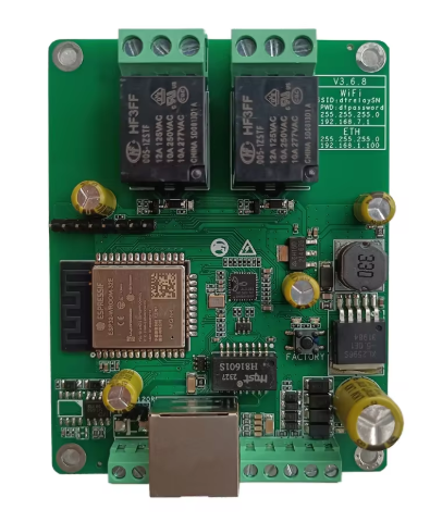
Description
Dingtian relay boards are ESP32 based boards with 2, 4, 8, 16, 24 or 32 relays and inputs.
At the 2 and 4 relay boards the relays and inputs are directly connected to the gpio’s of the ESP32.
MQTT Messages
Inputs state are reported through SENSOR message at teleperiod:
MQT: tele/dingtian1/SENSOR = "{"Time":"2024-04-26T09:17:15","Switch1":"ON","Switch2":"ON"}"
Input changes are only reported when using switchmode 15 or 16:
MQT: stat/dingtian1/SENSOR = {"Time":"2024-04-26T09:24:02","Switch1":"OFF","Switch2":"ON"} (retained)
When using switchmode 0, Input changes are not reported, but the output changes are reported:
MQT: stat/dingtian1/RESULT = {"POWER1":"ON"}
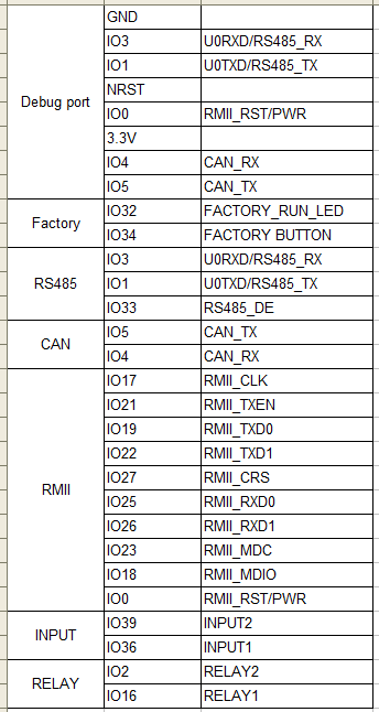
RS-485
RS-458 is handled by a BL3085(I47) RS-485 chip which is half duplexn and needs explicit flow control toggling. The /RE and DE pins are tied together and are available on GPIO33 (this differs from the pinout map upper right hand side which says 13 but is wrong), high is send mode.
Ethernet
To use ethernet JL1101 use the template provided or you must set GPIO0 ETH-Power GPIO18 ETH-MDIO GPIO23 ETH-MDC
and commands: EthType 7 (JL1101) ethernet 1
GPIO
Note
For using Modbus on the RS485 port (if ordered with this option) have a look at https://tasmota.github.io/docs/Modbus-Bridge/ and also add #define USE_MODBUS_BRIDGE and if desired #define USE_MODBUS_BRIDGE_TCP to user_config_override.h