


Available from:
Aliexpress.com
Manufacturer:
Dingtian-tech.com
Install method:
USB to Serial
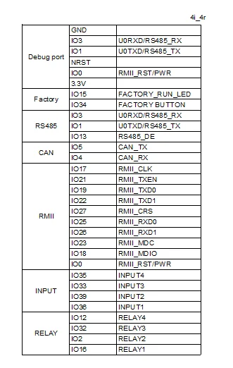
| GPIO # | Component |
|---|---|
| GPIO00 | None |
| GPIO01 | ModBr Tx |
| GPIO02 | Relay 2 |
| GPIO03 | ModBr Rx |
| GPIO04 | None |
| GPIO05 | None |
| GPIO09 | None |
| GPIO10 | None |
| GPIO12 | Relay 4 |
| GPIO13 | ModBr Tx Ena |
| GPIO14 | None |
| GPIO15 | None |
| GPIO16 | Relay 1 |
| GPIO17 | None |
| GPIO18 | ETH MDIO |
| GPIO19 | None |
| GPIO20 | None |
| GPIO21 | None |
| GPIO22 | None |
| GPIO23 | ETH MDC |
| GPIO24 | None |
| GPIO25 | None |
| GPIO26 | None |
| GPIO27 | None |
| GPIO6 | None |
| GPIO7 | None |
| GPIO8 | None |
| GPIO11 | None |
| GPIO32 | Relay 3 |
| GPIO33 | Switch 3 |
| GPIO34 | None |
| GPIO35 | Switch 4 |
| GPIO36 | Switch 1 |
| GPIO37 | None |
| GPIO38 | None |
| GPIO39 | Switch 2 |
{"NAME":"Dingtian DT-R004","GPIO":[0,9408,225,9440,0,0,0,0,227,9952,0,0,224,0,5600,0,0,0,0,5568,0,0,0,0,0,0,0,0,226,162,0,163,160,0,0,161],"FLAG":0,"BASE":1}Warning
When ordering this board ask for relay board with test firmware, otherwise the ESP32 will be locked.
Relay 1 is connected to GPIO 16 which is used for PSRAM in Tasmota, to prevent a pulse on Relay 1 upon boot use the tasmota32-nopsram firmware (https://github.com/arendst/Tasmota/discussions/21266), or use “#define DISABLE_PSRAMCHECK true” in user_config_override.h upon building.
Description
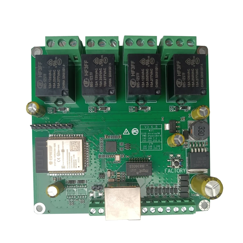
Dingtian relay boards are ESP32 based boards with 2, 4, 8, 16, 24 or 32 relays and inputs.
At the 2 and 4 relay boards the relays and inputs are directly connected to the gpio’s of the ESP32.
Example for the 4 relay board:
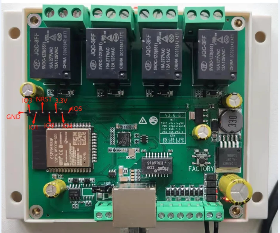
Pinout for the 4 relay board:
MQTT Messages
Inputs state are reported through SENSOR message at teleperiod:
MQT: tele/dingtian1/SENSOR = "{"Time":"2024-04-26T09:17:15","Switch1":"ON","Switch2":"ON","Switch3":"ON","Switch4":"ON"}"
Input changes are only reported when using switchmode 15 or 16:
MQT: stat/dingtian1/SENSOR = {"Time":"2024-04-26T09:24:02","Switch1":"OFF","Switch2":"ON","Switch3":"OFF","Switch4":"OFF"} (retained)
When using switchmode 0, Input changes are not reported, but the output changes are reported:
MQT: stat/dingtian1/RESULT = {"POWER1":"ON"}
Note
For using Modbus on the RS485 port (if ordered with this option) have a look at https://tasmota.github.io/docs/Modbus-Bridge/ and also add #define USE_MODBUS_BRIDGE and if desired #define USE_MODBUS_BRIDGE_TCP to user_config_override.h