


Available from:
Aliexpress.com
Manufacturer:
Dingtian-tech.com
Install method:
USB to Serial
| GPIO # | Component |
|---|---|
| GPIO00 | User |
| GPIO01 | ModBr Tx |
| GPIO02 | User |
| GPIO03 | ModBr Rx |
| GPIO04 | User |
| GPIO05 | User |
| GPIO09 | User |
| GPIO10 | User |
| GPIO12 | User |
| GPIO13 | Dingtian SDI |
| GPIO14 | Dingtian CLK 2 |
| GPIO15 | Dingtian RCK |
| GPIO16 | Dingtian Q7 |
| GPIO17 | User |
| GPIO18 | User |
| GPIO19 | User |
| GPIO20 | None |
| GPIO21 | User |
| GPIO22 | User |
| GPIO23 | User |
| GPIO24 | None |
| GPIO25 | User |
| GPIO26 | User |
| GPIO27 | User |
| GPIO6 | None |
| GPIO7 | None |
| GPIO8 | None |
| GPIO11 | None |
| GPIO32 | Dingtian PL |
| GPIO33 | ModBr Tx Ena |
| GPIO34 | User |
| GPIO35 | User |
| GPIO36 | User |
| GPIO37 | None |
| GPIO38 | None |
| GPIO39 | User |
{"NAME":"Dingtian DT-R008","GPIO":[1,9408,1,9440,1,1,1,1,1,9760,9729,9856,9792,1,1,1,0,1,1,1,0,1,1,1,0,0,0,0,9824,9952,1,1,1,0,0,1],"FLAG":0,"BASE":1}Warning
When ordering this board ask for relay board with test firmware, otherwise the ESP32 will be locked.
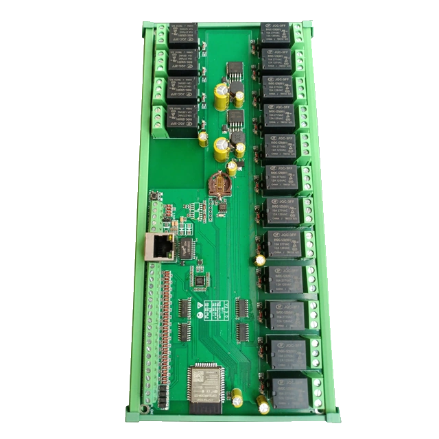
Dingtian relay boards are ESP32 based boards with 8, 16, 24 or 32 relays and inputs. Relays are driven through x595 shift registers and inputs are read from x165 shift registers Because the design is using some GPIO for both ‘595 and ‘165, those are not independent and could not be managed through the existing Shift595 driver
This driver is not included in any official Tasmota build. You must compile your own build by adding the following line in your user_config_override.h:
#define USE_DINGTIAN_RELAY
The driver define 5 News GPIOs (from here):
|                   |  8-relay | 16-relay | 32-relay | Description                                                |
|-------------------+----------+----------+----------+------------------------------------------------------------|
| GPIO_DINGTIAN_CLK | GPIO 14  | GPIO 14  | GPIO 14  | Serial clokc for both 595 and 165                          |
|    CLK Index      |    1     |    2     |   4      | Number of 74HC165 and 74HC595                              |
| GPIO_DINGTIAN_SDI | GPIO 13  | GPIO 13  | GPIO 13  | Serial input for 595                                       |
| GPIO_DINGTIAN_Q7  | GPIO 16  | GPIO 35  | GPIO 35  | Serial output of 165                                       |
| GPIO_DINGTIAN_PL  | GPIO 32  | GPIO 0   | GPIO 0   | Latch 165 inputs (but also controls OE of the 595)         |
| GPIO_DINGTIAN_RCK | GPIO 15  | GPIO 15  | GPIO 15  | Latch of 595 outputs (but also control CLK inhibit of 165) |
The CLK GPIO supports index 1 to 4 to specify the number of shift registers:
- 1 : 8 relays/inputs boards
- 2 : 16 relays/inputs boards
- 3 : 24 relays/inputs boards (not really existing)
- 4 : 32 relays/inputs boards
Example for the 8 relay board:


WebGUI:

Inputs state are reported through SENSOR message at teleperiod like for PCF8574/MCP230xx port extenders:
21:46:07.760 MQT: tele/dingtian1/SENSOR = {"Time":"2022-10-29T21:46:07+02:00","DINGTIAN":{"IN1":1,"IN2":1,"IN3":1,"IN4":1,"IN5":1,"IN6":1,"IN7":1,"IN8":1}} (retained)
And changes are reported to DINGTIAN_CHG topic:
21:46:50.665 MQT: stat/dingtian1/DINGTIAN_CHG = {"Time":"2022-10-29T21:46:50+02:00","DINGTIAN_CHG":{"IN1":0,"IN2":0,"IN3":0,"IN4":0,"IN5":0,"IN6":0,"IN7":0,"IN8":0}}
The driver is limited to ESP32 as the Dingtian boards only use ESP32, however if needed the limit could be removed in order to use the same principle on a ESP8266 custom board.
See https://github.com/arendst/Tasmota/pull/17032 for more info.