


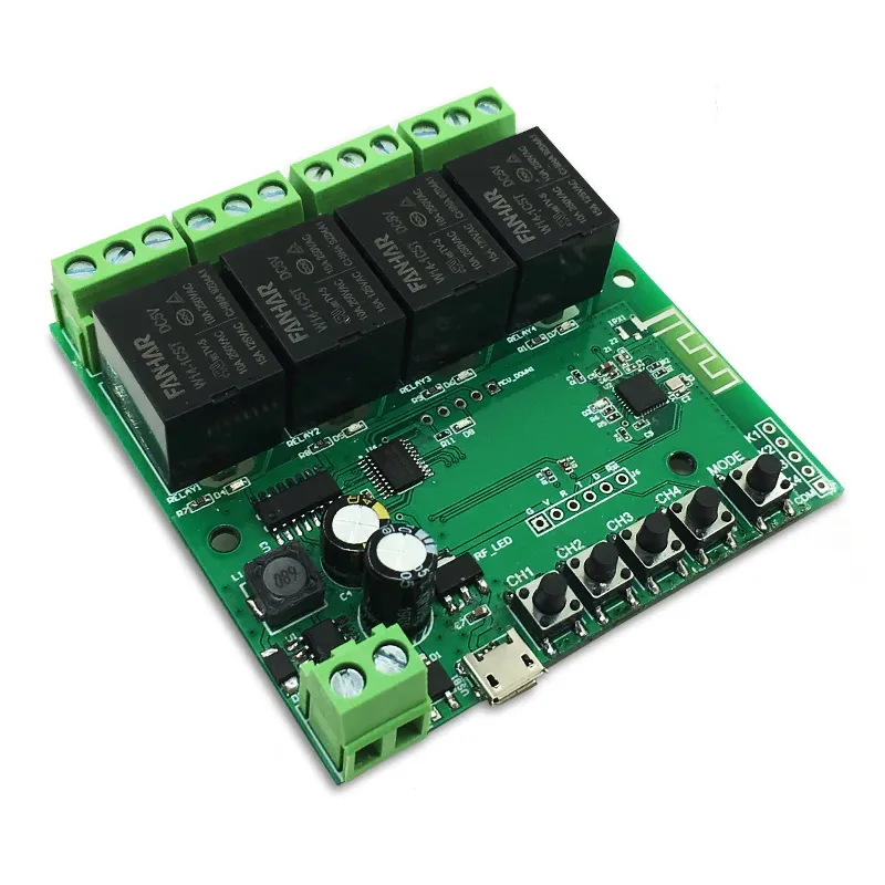
Eachen ST-DC4 Relay Board
Available from:
Amazon.com
Aliexpress.com
Manufacturer:
Tuya.eachen.cc
Install method:
USB to Serial
| GPIO # | Component |
|---|---|
| GPIO00 | Switch 1 |
| GPIO01 | User |
| GPIO02 | User |
| GPIO03 | User |
| GPIO04 | Relay 3 |
| GPIO05 | Relay 2 |
| GPIO09 | User |
| GPIO10 | User |
| GPIO12 | Relay 1 |
| GPIO13 | LedLink |
| GPIO14 | User |
| GPIO15 | Relay 4 |
| GPIO16 | User |
| GPIO17 | None |
Configuration
{"NAME":"Eachen_ST-DC4","GPIO":[160,1,1,1,226,225,1,1,224,544,1,227,1,0],"FLAG":0,"BASE":54}Serial Flashing
Flash the Tasmota firmware.
- Get the latest Tasmota firmware.
- Use Tazmotizer for flashing via serial interface.
- Start Tasmotizer.
- Select Serial Port.
- Check Save original firmware.
- Pick 1 MB from dropdown list.
- Select BIN radio button.
- Open latest Tasmota firmware from above.
- Check Erase before flashing.
- Connect USB to serial interface from computer to board with 3v jumper selected.
- Connect to board as follows.
| USB Adapter | Eachen Board |
|---|---|
| VCC | V |
| GND | G |
| TXD | R |
| RXD | T |
- Power up the Eachen Relay board with the #1 Relay button held down.
- Continue holding the #1 Relay button down during the entire flashing process.
- Hit blue Tasmotize! button in Tasmotizer. 4.1 If Tasmotizer times out with error message: ‘Failed to connect to ESP8266: Timed out waiting for packet header’, you may have to connect the 2 C66 pads on the ST-DC4 and repeat steps 2 to 4
- After a minute or so the Eachen board will reboot into new firmware.
- Unplug power from Eachen board. Wait 5 secs then replug power.
Connect to WIFI
- Using WIFI capable device connect to AP labeled tasmota_XXXXXX.
(where XXXXXX is the last 6 digits of the device’s MAC addr.) - Once connected go to http://192.168.4.1
- Enter your WIFI information into AP1 SSID and AP1 Password and check the box beside password.
- Hit Save.
- Using WIFI capable device connect to AP labeled tasmota_XXXXXX.
Setup
- Go to your Router Admin page.
- Look for IP address of device named tasmota_XXXXXX.
(where XXXXXX is the last 6 digits of device’s MAC addr.)
- Look for IP address of device named tasmota_XXXXXX.
- Enter the IP address from above into a web browser.
- Go to Configuration, Other
- (This step:
- configures the device’s parameters including TuyaMCU serial COMM and 4 dummy relays used in the Rules below)
- Copy
{"NAME":"Eachen_ST-DC4","GPIO":[160,1,1,1,226,225,1,1,224,544,1,227,1,0],"FLAG":0,"BASE":54} - Paste into Template field.
- Check Activate box.
- Hit Save.
- Device will reboot.
- Go to Console
- (This step sets up:
- 9600 baud rate with
so97 0 - enables MQTT with
so3 1 - publishes TuyaReceived messages to MQTT with
so66 1 - keeps momentary timing slider from turning off dummy relay9(BUS) with
so77 1 - keeps momentary timing slider from turning on dummy relay9(BUS) with
so20 1 - assigns the Tuya MCU serial relay devices to Tasmota devices
- relay1 with
tuyamcu 11,1 - relay2 with
tuyamcu 12,2 - relay3 with
tuyamcu 13,3 - relay4 with
tuyamcu 14,4 - all on function with
tuyamcu 15,13 - momentary timing slider with
tuyamcu 21,103)
- relay1 with
- Copy
backlog so97 0;so3 1;so66 1;so20 1;so77 1;tuyamcu 11,1;tuyamcu 12,2;tuyamcu 13,3;tuyamcu 14,4;tuyamcu 15,13;tuyamcu 21,103 - Paste into Console’s Enter command space.
- Device will reboot.
- Go to Console
- (This step sets up:
- an interlock on dummy relays 6(SLM),7(MAM),8(ILKM) so only 1 relay mode may be selected with
interlock 6,7,8andinterlock 1 -
0 to 60 secs timing on momentary timing slider with
dimmerrange 0,600anddimmerstep 5) - Copy
backlog interlock 6,7,8;interlock 1;dimmerrange 0,600;dimmerstep 5 - Paste into Console’s Enter command space.
- Device will reboot.
- Go to Console
- (This step:
- names all the WebUI buttons using the first Copy/Paste
- ALL = ALL ON button
- SLM = Self Lock Mode (any number of relays remain ON until turned OFF)
- MAM = Momentary Mode (uses Dimmer Slider to set ON time length from 0 to 60 secs)
- ILKM = Interlock Mode (Only 1 relay can remain ON at a time)
- BUS = Boot Up State (Do all relays remain OFF or turn ON when power is applied to board)
- creates Rules to be used for
- Boot Up State with Rule1 and
- Relay Mode with Rule2
using the second Copy/Paste)
- Copy
backlog webbutton5 ALL;webbutton6 SLM;webbutton7 MAM;webbutton8 ILKM;webbutton9 BUS - Paste into Console’s Enter command space.
- Copy
backlog rule1 on power9#state=1 do tuyasend1 101,1 endon on power9#state=0 do tuyasend1 101,0 endon;rule1 1;rule2 on power6#state=1 do tuyasend4 102,0 endon on power7#state=1 do tuyasend4 102,1 endon on power8#state=1 do tuyasend4 102,2 endon on tuyareceived#data=55AA03070005660400010079 do power6 1 endon on tuyareceived#data=55AA0307000566040001017A do power7 1 endon on tuyareceived#data=55AA0307000566040001027B do power8 1 endon;rule2 1 - Paste into Console’s Enter command space.
- Device will reboot.
- optional - Go to Console
- (This step:
- names all the devices)
- Copy
backlog devicename tasmota_relay01;friendlyname1 tasmota_relay01-1;friendlyname2 tasmota_relay01-2;friendlyname3 tasmota_relay01-3;friendlyname4 tasmota_relay01-4;friendlyname5 tasmota_relay01-all;friendlyname6 tasmota_relay01-slm;friendlyname7 tasmota_relay01-mam;friendlyname8 tasmota_relay01-ilkm - Paste into Console’s Enter command space.
- (This step: