Available from:
Amazon.co.uk
Manufacturer:
Electriq.co.uk
Install method:
USB to Serial
| GPIO # | Component |
|---|---|
| GPIO00 | None |
| GPIO01 | Tuya Tx |
| GPIO02 | None |
| GPIO03 | Tuya Rx |
| GPIO04 | None |
| GPIO05 | None |
| GPIO09 | None |
| GPIO10 | None |
| GPIO12 | None |
| GPIO13 | None |
| GPIO14 | None |
| GPIO15 | None |
| GPIO16 | None |
| GPIO17 | None |
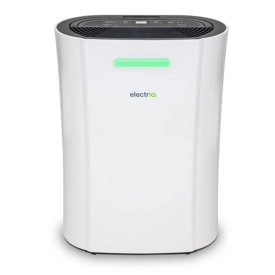
{"NAME":"electriQ CD12PW","GPIO":[0,2272,0,2304,0,0,0,0,0,0,0,0,0,0],"FLAG":0,"BASE":54}This is a Tuya dehumidifier. There is also a larger unit in the same range, the CD20PRO-LE, so these instructions will likely work for that too.
MCU Product ID: tns1hza48otl6oiz1.0.0
OTA Flashing
I tried flashing with Tuya Convert (2.4.4) but it did not work, so I needed to flash via serial, and hence locate and extract the TYWE3S chip.
Extracting the TYWE3S chip
- Disconnect mains power.
- Remove the water tank (if the unit has been running) so nothing spills out when the electronics are exposed.
- Looking at the rear of the unit, there are four recessed screws down each side that you need to remove.
- With the screws removed, the front panel (i.e. with the light and the logo) should come away in one piece.
- The front panel will still be attached to the main unit via a cable connecting the light, but there’s a JST-SM-style inline connector you can unplug to free the front panel completely.
- With the front panel out of the way, and looking into the exposed front of the unit, locate the sealed plastic box at the bottom left, next to the compressor, with lots of cables running into it. This contains the electronics, including the TYWE3S chip we need to flash. But it also contains mains voltage terminals and capacitors, so be careful.
- There are two screws you’ll need to remove fastening the box to the main unit.
- With the screws removed, you should have enough cable slack to slide the box out of the front of the unit.
- The box itself is held closed by a single screw near the centre of the lid, which you need to remove, and four clips that need opening (you will need to use a flat head screwdriver) around the outside of the lid.
- Inside the box, the TYWE3S is secured by single screw in its corner, and connected to the main board via ribbon cable attached to a header.
- Remove the screw from the TYWE3S and remove the cable from the header on the TYWE3S side. The chip should now be free and ready to flash.
Serial Flashing
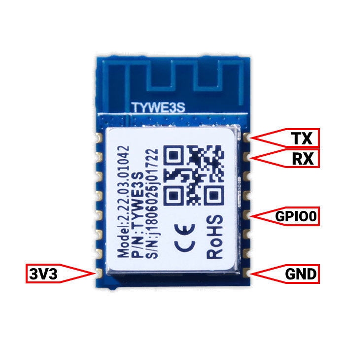
Since the chip has a header, it’s trivial to connect the GND, TX and RX pins to your USB-to-serial adapter via Dupont cables. However, the header power pin is labelled 5V (not the 3V3 required by the chip) and there’s no GPIO0 on the header. So you’ll need to connect the 3V3 and GPIO0 direct to the chip (e.g. with pincer probes). See TYWE3S pinout.
Note: The header is marked with what pins it expects as input, not what pins it connects to on the chip. In other words, you’ll need to connect the pin marked RX on the header to the RX pin on your USB-to-serial adapter, not RX to TX.
With everything connected you can now flash the chip - and then replace it and reassemble the unit.
Device Configuration
Please read TuyaMCU article to understand the terminology and configuration process. Then apply this template.
Functions
dpID 1Booleancontrols device power - turns the device on/offdpID 2Enumsets mode.0Dehumidify and Purify1Purify Only.
dpID 3Integercurrent humidity.dpID 4Integertarget humidity.dpID 5Booleanhas no effect.dpID 10Booleanhas no effect.dpID 101Booleanturns humidity indicator light on/off (shows green/orange/red depending on how healthy the current humidity level is).dpID 102Enumhas no effect.dpID 103Integercurrent temperature.dpID 104Booleanhas no effect.
Configuration
Next we need to map the above to their respective Tasmota functions.
backlog TuyaMCU 11,1; TuyaMCU 61,2; TuyaMCU 73,3; TuyaMCU 21,4; TuyaMCU 12,101; TuyaMCU 71,103; TuyaMCU 99,5; TuyaMCU 99,10; TuyaMCU 99,102; TuyaMCU 99,104; SetOption20 1; SetOption54 1;
Note: Dimmer maps to dpID4 for target humidity select (its better to use console commands to be more precise). SetOption20 1 and SetOption54 1 stop the dimmer from controlling the power.
Label webUI buttons:
backlog webbutton1 Power; webbutton2 Indicator Light;
Set the proper temperature and humidity resolutions:
backlog TempRes 0; HumRes 0;
TuyaEnum
As of Tasmota 9.1.0.1 #9769 it is possible to map Type4 dpIDs (such as dpID2) to an Enum fn ID.
Map dpID2 to Enum1:
TuyaMCU 61,2
Set Enum1 range (in this case, to allow values 0 and 1 only).
TuyaEnumList 1,1
Now you can control the mode with TuyaEnum1 <x> where x is 0 or 1. If you try a number outside the Enum1 range it will throw an error.
Pinout
 .
.


