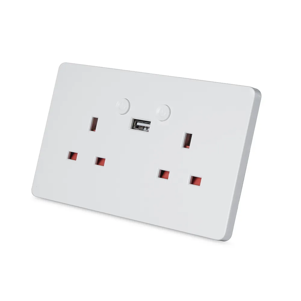
Available from:
Amazon.co.uk
Bltdirect.com
Manufacturer:
Ener-j.co.uk
Install method:
Tuya-Convert
| GPIO # | Component |
|---|---|
| GPIO00 | Button1 |
| GPIO01 | None |
| GPIO02 | None |
| GPIO03 | None |
| GPIO04 | None |
| GPIO05 | Relay1 |
| GPIO09 | Button2 |
| GPIO10 | None |
| GPIO12 | Relay2 |
| GPIO13 | Led1i |
| GPIO14 | None |
| GPIO15 | None |
| GPIO16 | None |
| FLAG | None |
{"NAME":"Ener-J 2-Gang ","GPIO":[17,0,0,0,0,21,18,0,22,56,0,0,0],"FLAG":0,"BASE":18}Tuya-Convert might not be possible for this device since the template was added (2020-02-20).
Left Hand Socket is Button 1
There may be different versions where the relays are inverted and this template is required:
{"NAME":"Ener-J 2-Gang ","GPIO":[33,0,0,0,0,224,32,0,225,320,0,0,0,0],"FLAG":0,"BASE":18}
There is a blue LED above the earth pin of each socket; these light when the corresponding socket is powered.
Neither of these templates controls power to the USB socket. It is always powered, the 5V on the USB socket is also used to power the processor via a 3v3 regulator.
There is a green LED above the USB socket; this comes on if either 13A socket is powered.
To disable the Green LED always use this template instead :
{""NAME"":""Ener-J 2-Gang "",""GPIO"":[17,0,0,0,0,21,18,0,22,0,0,0,0],""FLAG"":0,""BASE"":18}
The Green LED is very bright on these devices as an option controlling it with the LEDLinki will allow the LED to flash during WiFi connection and the go OFF once connected. This also maintains the flash indication of button pushed.
{""NAME"":""Ener-J 2-Gang "",""GPIO"":[17,0,0,0,0,22,18,0,21,158,0,0,0],""FLAG"":0,""BASE"":18}
When flashing these devices via the serial interface, there are a number of pads on the reverse on the PCB for easy connection. GPIO0 is available on a pad, but is also connected to S1. Caution when using the power pad marked +5V, it is okay to apply +5V on the pad but make sure that you do not exceed 3.3V on the serial pins connected to TX and RX on the processor. A D-SUN USB to TTL interface was used to program the device. It provides both +5V and 3.3V and limits the TX and RX signals.


