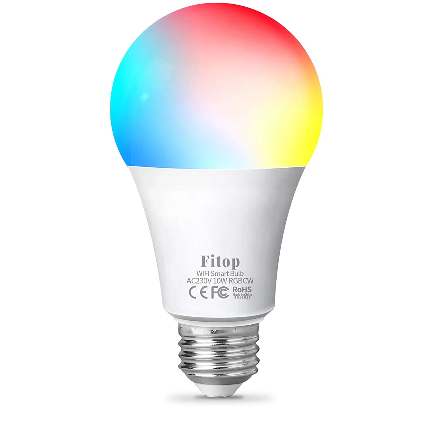
Available from:
Amazon.de
Install method:
USB to Serial
| GPIO # | Component |
|---|---|
| GPIO00 | None |
| GPIO01 | None |
| GPIO02 | None |
| GPIO03 | None |
| GPIO04 | None |
| GPIO05 | None |
| GPIO09 | None |
| GPIO10 | None |
| GPIO12 | None |
| GPIO13 | SM2135 CLK |
| GPIO14 | SM2135 DAT |
| GPIO15 | None |
| GPIO16 | None |
| GPIO17 | None |
{"NAME":"Fitop 10W RGBCW","GPIO":[0,0,0,0,0,0,0,0,0,4032,4064,0,0,0],"FLAG":0,"BASE":18,"CMND":"SetOption37 6"}This device now comes with a Wi-Fi module incompatible with Tasmota
Tuya-Convert does not work.
Bulb has a metal lid under the LED PCB that needs to be removed before the TYWE3L module is accessible.
I had success by removing the metal cap at the socket:
This can be done by slipping a sharp metal blade between the edge and the plastic, then carefully lifting it out. There is a wire wedged in there, don’t let it slip into the bulb.
Then, use a hardened metal rod (about 2 mm in diameter) by threading it into the hole at an angle, being careful not to damage or apply pressure to the components on the PCB, to push the lid off with a press or a vice.
The metal is rather soft, you can puncture it if you press too hard and you might have to repeat on different locations before it pops out.
Alternatively you can just Dremel the lid out, but it’s used for heat dissipation so it’s better to keep it intact and reinstall it after flashing.
The module is now easily accessible, and wires can be soldered on according to this pinout
On my bulbs after applying the template the Green and Blue channels were swapped, so ‘SetOption37 6’ needs to be set.
I flashed two bulbs successfully and without damaging them this way.


