


Available from:
Banggood.com
Aliexpress.com
Manomano.de
| GPIO # | Component |
|---|---|
| GPIO00 | Button1 |
| GPIO01 | None |
| GPIO02 | None |
| GPIO03 | None |
| GPIO04 | None |
| GPIO05 | Relay2 |
| GPIO09 | Button2 |
| GPIO10 | None |
| GPIO12 | Relay1 |
| GPIO13 | Led1 |
| GPIO14 | None |
| GPIO15 | None |
| GPIO16 | None |
| FLAG | Analog |
{"NAME":"Geekcreit 2ch","GPIO":[17,0,0,0,0,22,18,0,21,52,0,0,0],"FLAG":1,"BASE":18}Both AC and DC versions work the same. On DC version the pin marked 3v3 on the programming header is 5v.
**Note: ** The third button on this device is not connected to a GPIO. Instead it is used to cycle through some relay modes that are supported by the two external ICs. Only one of these modes works with Tasmota, so it is necessary to continue to press this button 3 until the relays can be controlled from the toggle buttons in the Tasmota web UI.
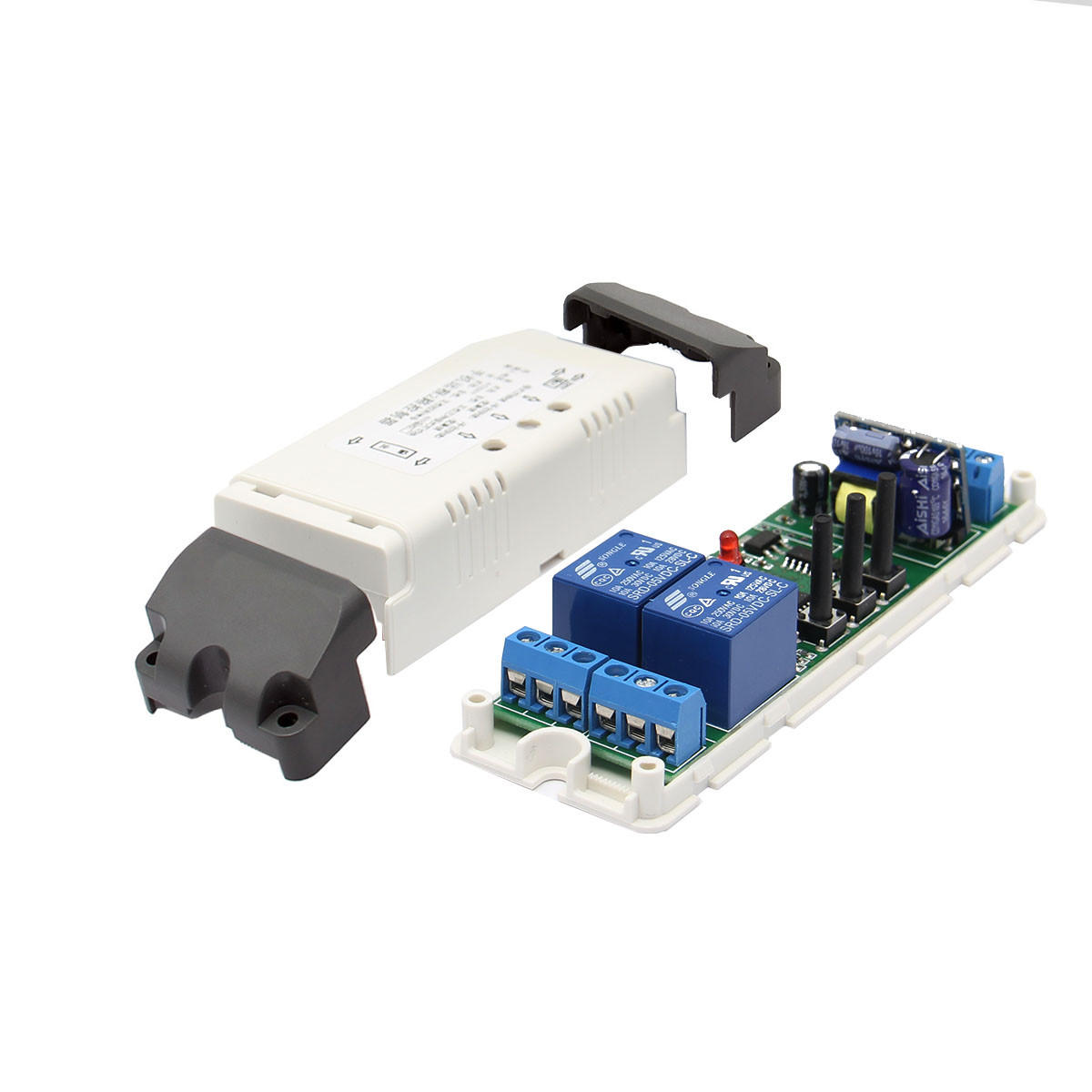
The Geekcreit/”Sonoff” 2CH is based on the ESP8285 via the Itead PSF-B04.
Serial Connection
Geekcreit/”Sonoff” 2CH
Please see the Hardware Preparation page for general instructions.
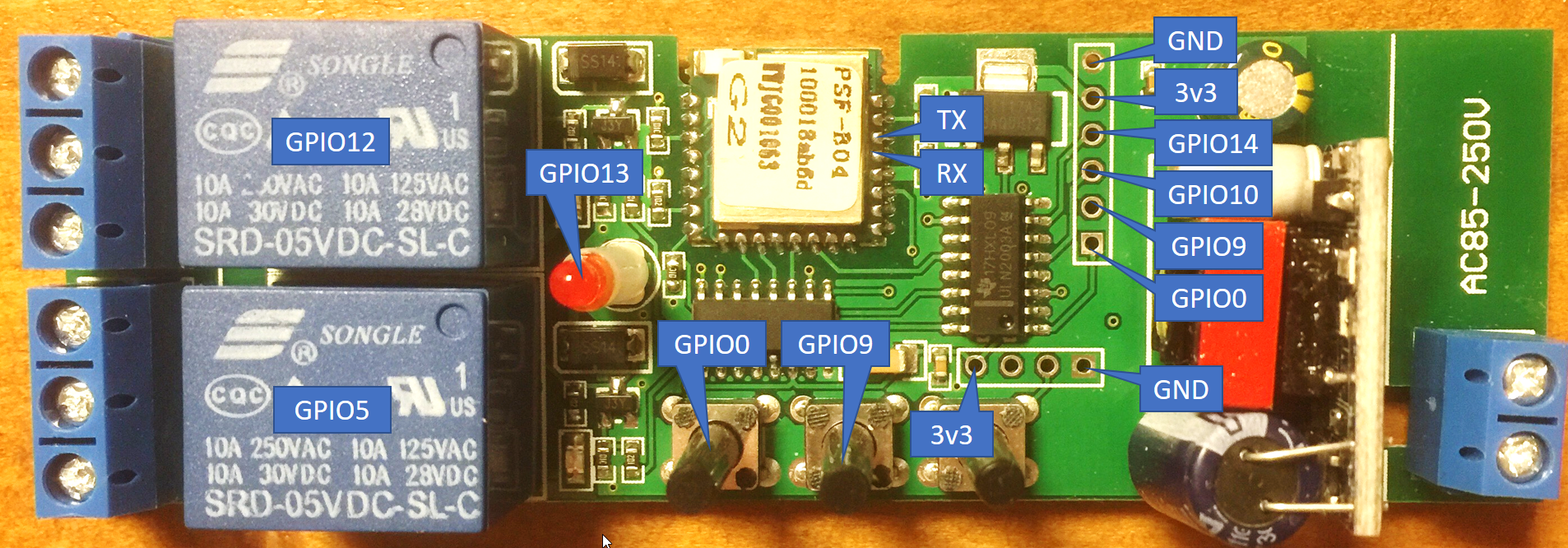
As always, you need to access the serial interface. The four serial pins (3V3, Rx, Tx, GND) can be seen in the picture. Unless you have a very steady hand soldering will be required for the TX and RX on the ESP chip.
Programming the Geekcreit/”Sonoff” 2CH is easy. The bottom left on-board-button is connected to GPIO0 and as with all ESP8266/ESP8285 modules pulling GPIO0 to GND is needed to put the chip in programming mode. You need to hold this button when booting the device for flashing.
Module parameters
Enable GPIO9 & GPIO10

To use GPIO9 and GPIO10 of the ESP8285, use command SetOption51 on.
Restart the module.
Pinout
 .
.