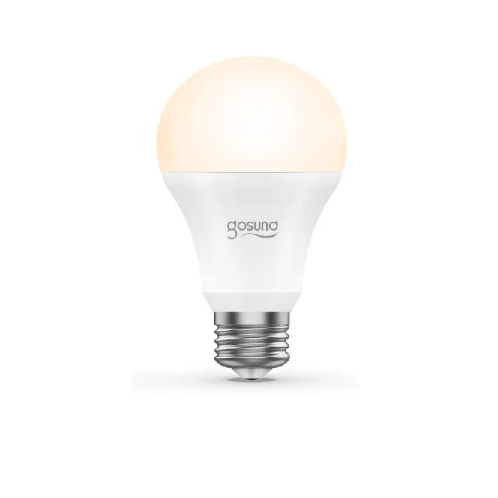
Available from:
Alza.de
Canadianbestseller.com
Us.gosund.com
Manufacturer:
Alibaba.com
Install method:
USB to Serial
| GPIO # | Component |
|---|---|
| GPIO00 | None |
| GPIO01 | None |
| GPIO02 | None |
| GPIO03 | None |
| GPIO04 | PWM 4 |
| GPIO05 | None |
| GPIO09 | None |
| GPIO10 | None |
| GPIO12 | PWM 1 |
| GPIO13 | PWM 2 |
| GPIO14 | PWM 3 |
| GPIO15 | None |
| GPIO16 | PWM 5 |
| GPIO17 | None |
{"NAME":"Gosund WB4","GPIO":[0,0,0,0,419,0,0,0,416,417,418,0,420,0],"FLAG":0,"BASE":18}This device now comes with a Wi-Fi module incompatible with Tasmota
See Tasmota documentation on how to configure RGBW lights to your needs.
Fitted with an ESP8285N08-derived “WB4-D 3.3.35 (P/N 8.05.000.0088)” device.
Disassembly: The middle contact of the E27 screw fixture can be lifted off by sliding a spudger between the plastic and metal points to release the tense wire. Pop off the plastic bulb and cut the blobs of adhesive to remove the main LED PCB. The ESP board will be accessible without removing it from the plastic casing.
Serial Flashing
Please see the Hardware Preparation page for general instructions.
The serial test points (3V3, RX, TX, GND) are available on the bottom of the controller board. Once disassembled you can easily access them to flash via serial.
Remember to put the chip into programming mode you will need to connect GPIO0 to GND during power up.


