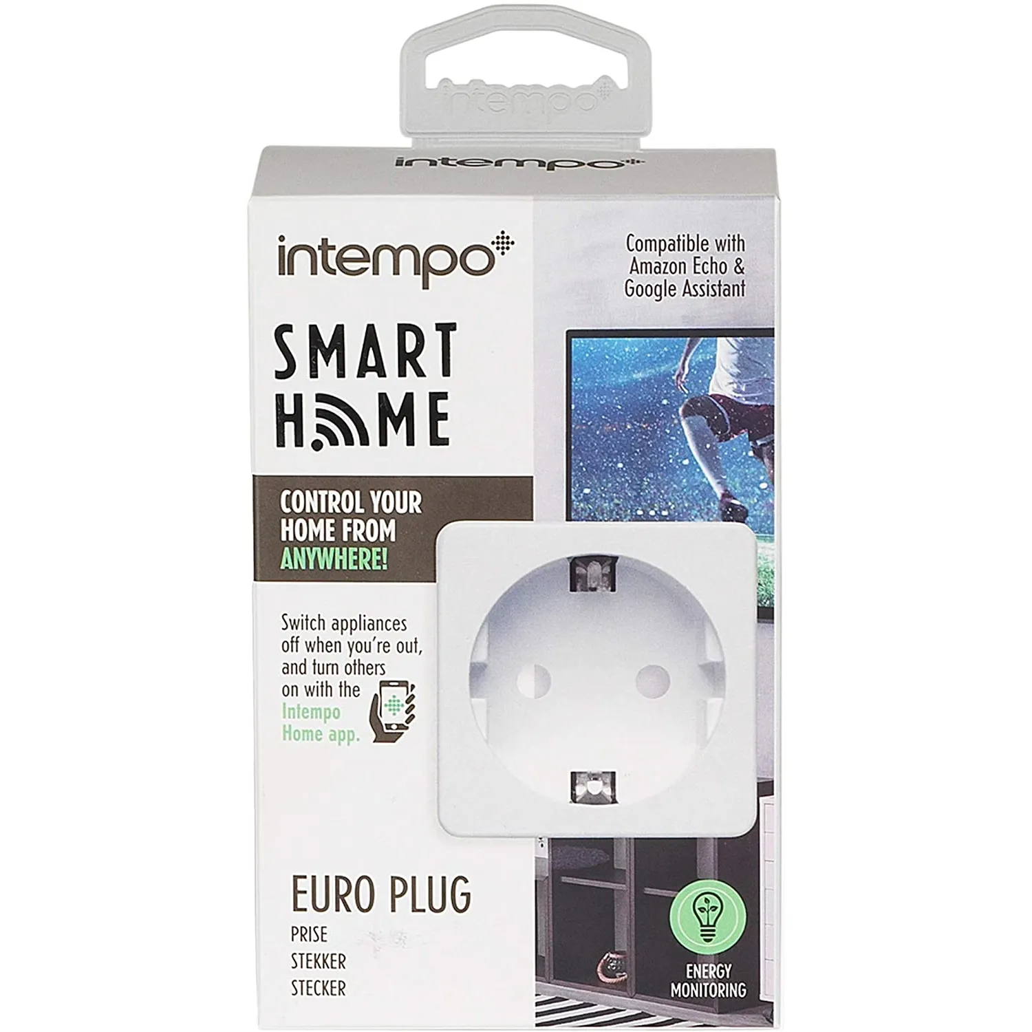
Available from:
Amazon.de
Install method:
USB to Serial
| GPIO # | Component |
|---|---|
| GPIO00 | None |
| GPIO01 | None |
| GPIO02 | None |
| GPIO03 | Button 1 |
| GPIO04 | None |
| GPIO05 | BL0937 CF |
| GPIO09 | None |
| GPIO10 | None |
| GPIO12 | None |
| GPIO13 | LedLinki |
| GPIO14 | Relay 1 |
| GPIO15 | None |
| GPIO16 | None |
| GPIO17 | None |
{"NAME":"Intempo EE5010WHTSTKEU","GPIO":[0,0,0,32,0,2720,0,0,0,576,224,0,0,0],"FLAG":0,"BASE":18}OPENING OF THE HOUSING:
The case is glued, therefore its pretty hard to open. Try to pry it open using a flat screwdriver or a flat bladed cutter knife all around the flat sides.
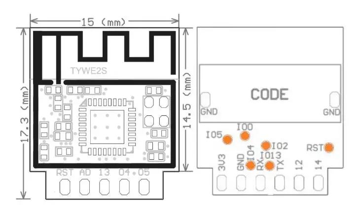
ACCESSING THE TYWE2S WiFi MODULE:
Option 1: With PCB removal
After that move that remove the thermal fuse from the relay. Otherwise it could break when soldering. Because next you need to remove the two female power pins. Afterwards the white cover can be clipped out. Next the two male power pins need to be unsoldered. Remove the main PCB and you get access to the TYWE2S WiFi Module.
Solder 4 wires (Vcc, GND, Rx, Tx) to the board, put GPIO 0 on TYWE2S to GND, and apply 3.3 V power for flashing.
Option 2: Without PCB removal
Try to access the Rx and Tx of the TYWE2S with wires which are shaped like hooks by pushing those between the housing and the PCB and afterwards pulling them gently so that the hooks touch the Rx and Tx connectors.
GPIO 0 on TYWE2S needs to be put to GND. For this just clamp a grounded wire between the TYWE2S and the capacitor in front of it.
Vcc (3.3 V) can be applied on the large contact between U2 and C5.
GND connector terminal is on the rear side of the TYWE2S.
Pinout
 .
.


