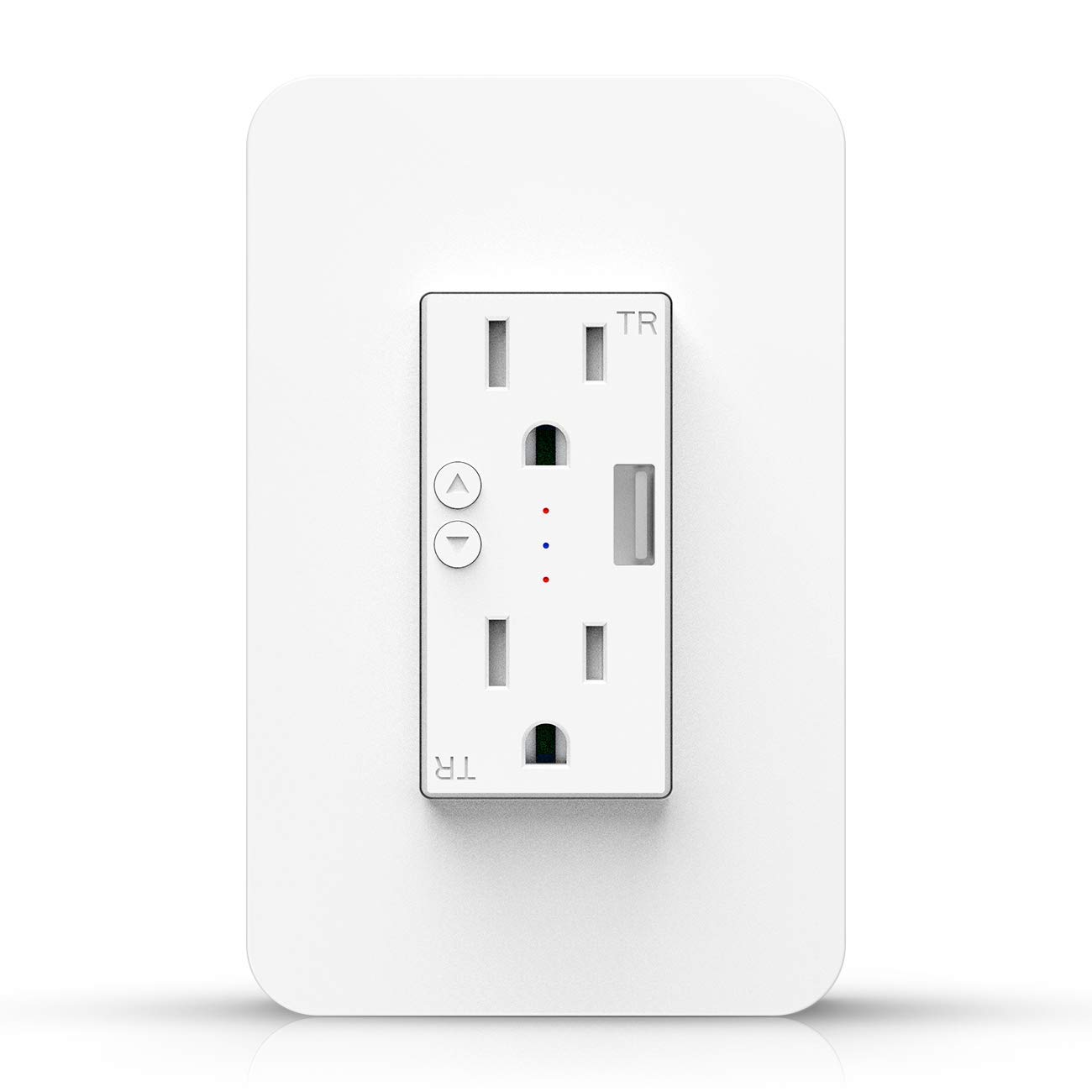
Available from:
Amazon.com
Alibaba.com
Amazon.com
Install method:
Tuya-Convert
| GPIO # | Component |
|---|---|
| GPIO00 | User |
| GPIO01 | User |
| GPIO02 | Relay3i |
| GPIO03 | User |
| GPIO04 | User |
| GPIO05 | Button2 |
| GPIO09 | None |
| GPIO10 | None |
| GPIO12 | Relay2 |
| GPIO13 | Relay1 |
| GPIO14 | User |
| GPIO15 | User |
| GPIO16 | Button1 |
| FLAG | Analog |
{"NAME":"KS-604S","GPIO":[255,255,31,255,255,18,0,0,22,21,255,255,17],"FLAG":1,"BASE":18}Tuya-Convert might not be possible for this device since the template was added (2019-03-09).
There are different versions of the KS-604S requiring different GPIO configurations. Please refer to https://tasmota.github.io/docs/devices/Kesen-KS-604S/ for more details.
2021-4-10 bought (2) KS-604S from amazon.com. OTA failed, flashed with internal pins. The template I had to use was the Other Device Template
{"NAME":"KS-604S","GPIO":[158,255,255,17,56,18,255,255,22,21,57,23,255],"FLAG":0,"BASE":18}
2021-10-07 Bought 1 on Amazon.ca and I had to Flash using onboard serial pin on the board. (vcc,tx,rx,gnd) some information say use D3 on J7 as GPIO-0 but this is not working. on the board just beside the ESP8266ex chip there is 1 solder point written ID0 it is located very near a capacitor. use that point to ground GPIO-0 during boot and flash Use the template: ‘{“NAME”:”KS-604S”,”GPIO”:[158,255,255,17,56,18,255,255,22,21,57,23,255],”FLAG”:0,”BASE”:18}’ this work perfectly having both socket working toggle 1 and 2 + USB toggle on #3


