Available from:
Amazon.com
Install method:
USB to Serial
| GPIO # | Component |
|---|---|
| GPIO00 | None |
| GPIO01 | None |
| GPIO02 | None |
| GPIO03 | None |
| GPIO04 | PWM 1 |
| GPIO05 | PWM 5 |
| GPIO09 | None |
| GPIO10 | None |
| GPIO12 | PWM 2 |
| GPIO13 | PWM 4 |
| GPIO14 | PWM 3 |
| GPIO15 | None |
| GPIO16 | None |
| GPIO17 | None |
{"NAME":"KHSUIN 13W BR30","GPIO":[0,0,0,0,416,420,0,0,417,419,418,0,0,0],"FLAG":0,"BASE":18}Comes with 2.0 firmware so serial flashing is necessary - no glue on shade so accessing the serial pads is easy.
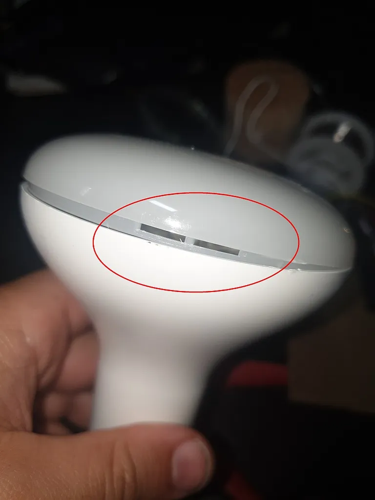
Opening the shade is straightforward but does require a bit of force and care to do it without leaving marks. It’s held on by 4 clips, so you need to use something thin but sturdy to push in under the edge of the shade, and then slide around to where the clip is to push it off and pop it up.
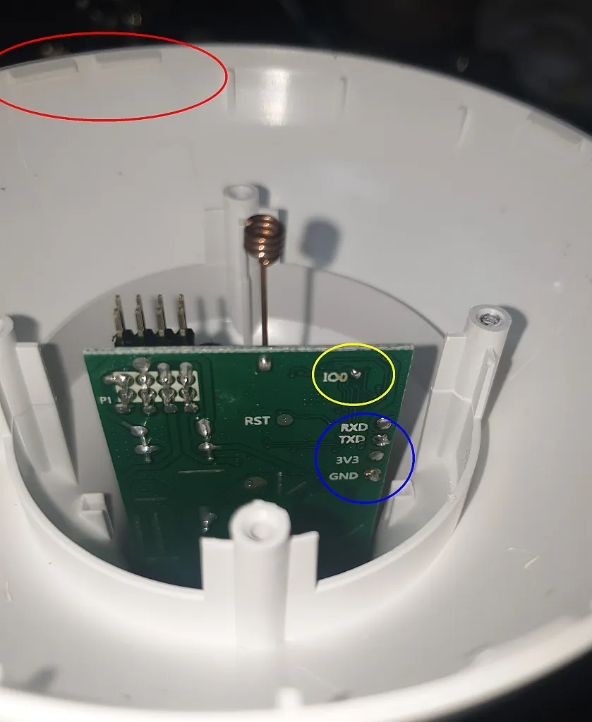
The red highlighted shows the shade slightly popped off, with 1 of the clips exposed.
Once it’s open, you can see the 4 clip points (red) and the exposed LED PCB has 2 screws (in green) which need to be removed.
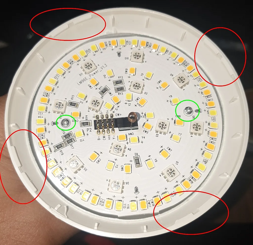
Once the screws are removed, you can tap it against the palm of your hand to slide the LED PCB off the pins and into your hand. Easiest way to remove it without damaging it.
After that, you have access to the esp PCB and the solder points (blue) on the back. Helpfully, GPIO0 has a solder point (IO0, yellow) as well, which you need to tie this to GND at power-on to get it into flash mode.
The RXD goes to your FTDI TX, TXD goes to your FTDI RX, 3v3 goes to the FTDI VCC/3.3v, and GND goes to the FTDI GND.
I soldered a small momentary switch in the middle of a wire to tie GPIO0 to GND, holding the button down, and then connecting the GND to the FTDI GND to get a successful connection.
You can optionally just hold down an extra wire from GND to the GPIO0 point during power on for a second or two. I think you can also just tie it to GND without needing it to be a momentary connection at power on, but be sure to remove that after flashing.
So for me, it was the following steps:
- Connect 3.3v/VCC, RX, TX to the FTDI
- Connect the FTDI to the USB port
- Hold down momentary button between GPIO0 and GND, connect GND to FTDI, wait 1-2 seconds before releasing button
- Open flash software and select correct serial/COM port, and hit flash
- After successful flash, unsolder all the wires, carefuly get the LED PCB back over top and seated onto the pins, screw down, and clip shade back into place
- DONE!