


Available from:
Aliexpress.com
Aliexpress.com
Alibaba.com
Manufacturer:
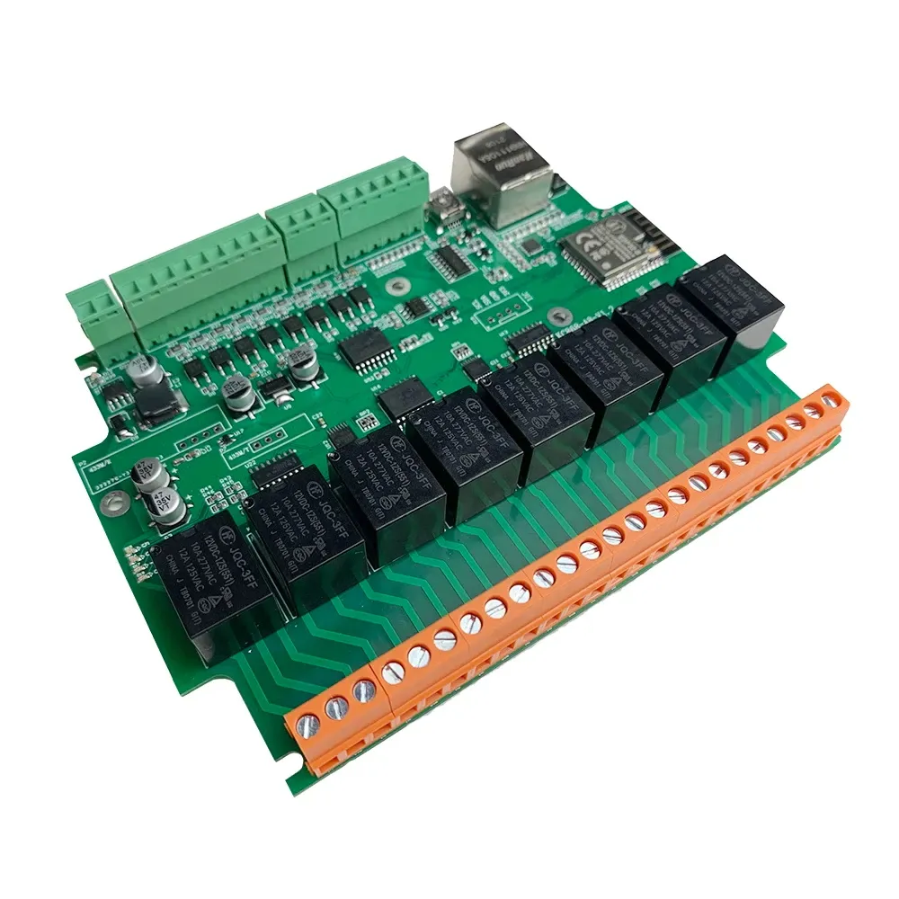
Kincony.com
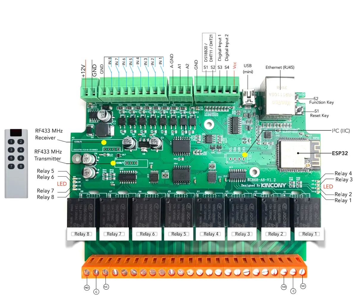
Install method:
USB to Serial
| GPIO # | Component |
|---|---|
| GPIO00 | Button 1 |
| GPIO01 | None |
| GPIO02 | RFSend |
| GPIO03 | None |
| GPIO04 | I2C SDA 1 |
| GPIO05 | I2C SCL 1 |
| GPIO09 | None |
| GPIO10 | None |
| GPIO12 | None |
| GPIO13 | User |
| GPIO14 | User |
| GPIO15 | RFrecv |
| GPIO16 | None |
| GPIO17 | None |
| GPIO18 | ETH MDIO |
| GPIO19 | None |
| GPIO20 | None |
| GPIO21 | None |
| GPIO22 | None |
| GPIO23 | ETH MDC |
| GPIO24 | None |
| GPIO25 | None |
| GPIO26 | None |
| GPIO27 | None |
| GPIO6 | None |
| GPIO7 | None |
| GPIO8 | None |
| GPIO11 | None |
| GPIO32 | User |
| GPIO33 | User |
| GPIO34 | None |
| GPIO35 | None |
| GPIO36 | User |
| GPIO37 | None |
| GPIO38 | None |
| GPIO39 | User |
{"NAME":"KC868-A8","GPIO":[32,0,1120,0,640,608,0,0,0,1,1,1152,0,0,5600,0,0,0,0,5568,0,0,0,0,0,0,0,0,1,1,0,0,1,0,0,1],"FLAG":0,"BASE":1,"CMND":"EthClockMode 3 | EthAddress 0 | EthType 0 | I2CDriver2 1"}Use the mini USB port to flash the device.
To build a binary with support for all features add to user_config_override.h:
#ifndef USE_I2C
#define USE_I2C                                  // I2C using library wire (+10k code, 0k2 mem, 124 iram)
#endif

  #define USE_PCF8574                            // [I2cDriver2] Enable PCF8574 I/O Expander (I2C addresses 0x20 - 0x26 and 0x39 - 0x3F) (+1k9 code)
    #define USE_PCF8574_SENSOR                   // enable PCF8574 inputs and outputs in SENSOR message
    #define USE_PCF8574_DISPLAYINPUT             // enable PCF8574 inputs display in Web page
    #define USE_PCF8574_MQTTINPUT                // enable MQTT message & rule process on input change detection : stat/%topic%/PCF8574_INP = {"Time":"2021-03-07T16:19:23+01:00","PCF8574-1_INP":{"D1":1}}

#define USE_ETHERNET                             // Add support for ethernet (Currently fixed for Olimex ESP32-PoE)
  #define ETH_TYPE          0                    // [EthType] 0 = ETH_PHY_LAN8720, 1 = ETH_PHY_TLK110, 2 = ETH_PHY_IP101
  #define ETH_ADDR          0                    // [EthAddress] 0 = PHY0 .. 31 = PHY31
  #define ETH_CLKMODE       3                    // [EthClockMode] 0 = ETH_CLOCK_GPIO0_IN, 1 = ETH_CLOCK_GPIO0_OUT, 2 = ETH_CLOCK_GPIO16_OUT, 3 = ETH_CLOCK_GPIO17_OUT

#define USE_RC_SWITCH                            // Add support for RF transceiver using library RcSwitch (+2k7 code, 460 iram)

#define USE_RF_SENSOR                            // Add support for RF sensor receiver (434MHz or 868MHz) (+0k8 code)
 #define USE_THEO_V2                            // Add support for decoding Theo V2 sensors as documented on https://sidweb.nl using 434MHz RF sensor receiver (+1k4 code)
 #define USE_ALECTO_V2                          // Add support for decoding Alecto V2 sensors like ACH2010, WS3000 and DKW2012 weather stations using 868MHz RF sensor receiver (+1k7 code)
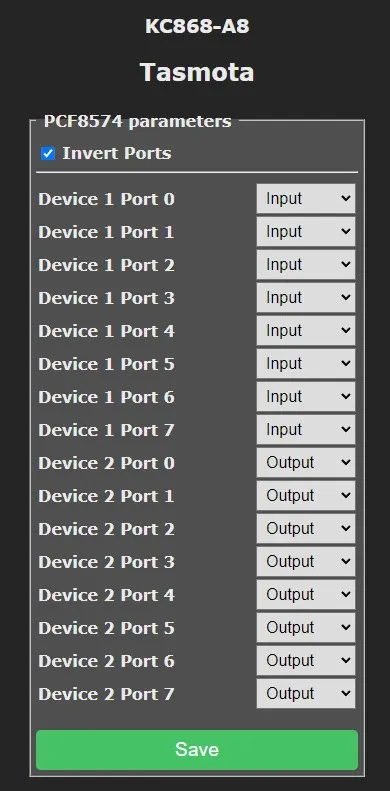
Relays and inputs (IN1 - IN8) use PCF8574 over I2C. You need to configure them using Configuration - Configure PCF8574 and set the PCF8574 connected to relays to Output.
To control relays with PCF8574 inputs you need to create rules for each input.
For example: Rule1 on PCF8574-1_INP#D0 do power1 %value% endon will mirror the value of the input with Relay1 aka PCF8574 output 0. Likewise you can use the same triggers to do other actions unrelated to relays.
Relays LEDs are tied to PCF8574 and cannot be controlled independently.
Useful Berry script to turn off Wi-Fi if Ethernet is connected. Place the code in autoexec.be:
tasmota.set_timer(30000,
  def()
    var eth = tasmota.eth().find('ip') != nil
    if tasmota.wifi().find('ip') != nil == eth
      tasmota.cmd('Wifi ' .. (eth ? 0 : 1))
    end
  end)
Kincony forums have examples and demos of all the functions with various firmware