KMC 70008 Switch

Available from:
Amazon.com
| GPIO # | Component |
|---|---|
| GPIO00 | Button1 |
| GPIO01 | User |
| GPIO02 | User |
| GPIO03 | None |
| GPIO04 | None |
| GPIO05 | User |
| GPIO09 | None |
| GPIO10 | None |
| GPIO12 | None |
| GPIO13 | Led1i |
| GPIO14 | Relay1 |
| GPIO15 | User |
| GPIO16 | User |
| FLAG | None |
Configuration (old format, will be converted to new template when applied)
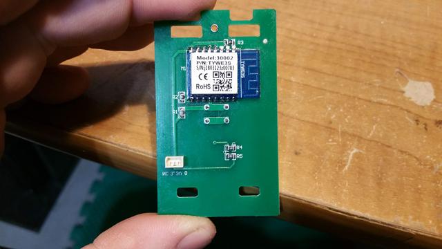
{"NAME":"KMC 70008","GPIO":[17,255,255,0,0,255,0,0,0,56,21,255,255],"FLAG":0,"BASE":18}I didn’t see any place to add pin headers, but the module has the usual ESP-12 pin layout, so I soldered right to the pins. You can skip soldering to GPIO 0 and just hold the button down when booting the device to get into flash mode.
The button is on GPIO 0, the relay and the white LED are on GPIO 14, the blue LED is on GPIO 13. When the blue LED on GPIO 13 is set to LED1i the white light shines when the relay is off and the blue light illuminates then the relay is on.