


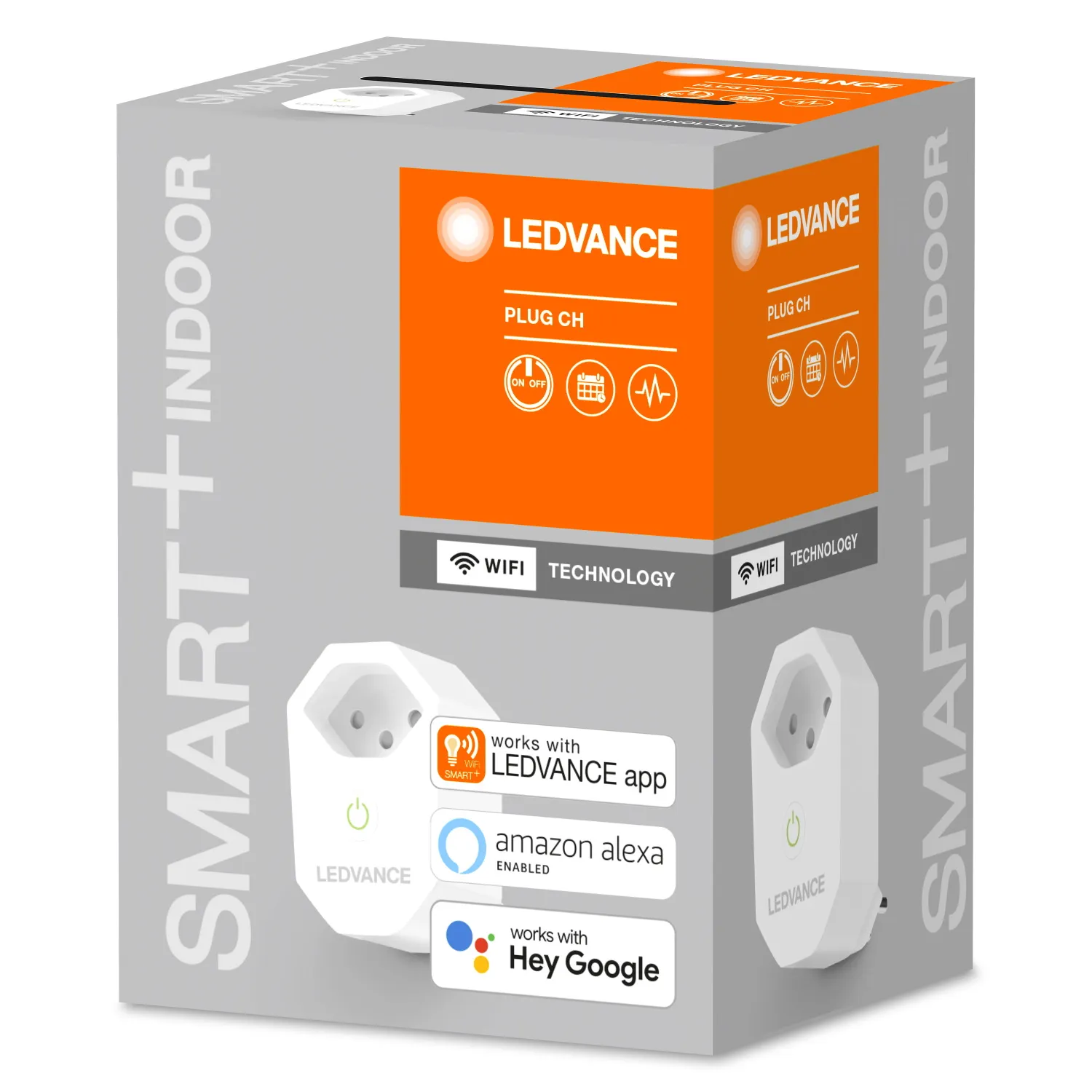
Ledvance Smart+ CH Power Monitoring Plug (4058075586444)
Available from:
Manufacturer:
Ledvance.com
Install method:
Replace module
| GPIO # | Component |
|---|---|
| GPIO00 | None |
| GPIO01 | None |
| GPIO02 | None |
| GPIO03 | Led 1 |
| GPIO04 | Button 1 |
| GPIO05 | None |
| GPIO09 | None |
| GPIO10 | None |
| GPIO12 | HLWBL CF1 |
| GPIO13 | Relay 1 |
| GPIO14 | BL0937 CF |
| GPIO15 | None |
| GPIO16 | None |
| GPIO17 | None |
Configuration
{"NAME":"Ledvance Plug CH","GPIO":[0,0,0,288,32,0,0,0,2656,224,2720,0,0,0],"FLAG":0,"BASE":18}
For more accurate energy consumption measurements this device requires power monitoring calibration.
This device uses WB2S module which needs to be replaced with ESP-02S, WT-01N or WT32C3-01N. Besides the module, this process will require a heat gun, soldering tools and moderate soldering skill.
This device uses WB2S module which needs to be replaced with ESP-02S, WT-01N or WT32C3-01N. Besides the module, this process will require a heat gun, soldering tools and moderate soldering skill.
This device is very similar to the EU version
It offers power metering with a BL0937 chip, however the voltage reading was only achievable by using the HLWBL CF1 component in the template.