LifeSmart Cololight PRO Hexagonal RGBIC LED (LS166)

Available from:
Banggood.com
Amazon.com
Amazon.de
Aliexpress.com
Install method:
USB to Serial
| GPIO # | Component |
|---|---|
| GPIO00 | None |
| GPIO01 | None |
| GPIO02 | None |
| GPIO03 | None |
| GPIO04 | Button 1 |
| GPIO05 | None |
| GPIO09 | None |
| GPIO10 | None |
| GPIO12 | None |
| GPIO13 | Button 2 |
| GPIO14 | None |
| GPIO15 | None |
| GPIO16 | WS2812 1 |
| GPIO17 | None |
| GPIO18 | None |
| GPIO19 | None |
| GPIO20 | None |
| GPIO21 | None |
| GPIO22 | None |
| GPIO23 | None |
| GPIO24 | None |
| GPIO25 | None |
| GPIO26 | None |
| GPIO27 | None |
| GPIO6 | None |
| GPIO7 | None |
| GPIO8 | None |
| GPIO11 | None |
| GPIO32 | None |
| GPIO33 | ADC Input 1 |
| GPIO34 | None |
| GPIO35 | None |
| GPIO36 | None |
| GPIO37 | None |
| GPIO38 | None |
| GPIO39 | None |
Configuration for ESP32
{"NAME":"Cololight PRO","GPIO":[0,0,0,0,32,0,0,0,0,33,0,0,1376,0,0,0,0,0,0,0,0,0,0,0,0,0,0,0,0,4704,0,0,0,0,0,0],"FLAG":0,"BASE":1}Each hex has 19 LEDs, use Pixels command to set the right number of LEDs.
Microphone is mapped to Analog input but there is no support for sound reactive effects in Tasmota.
Flashing
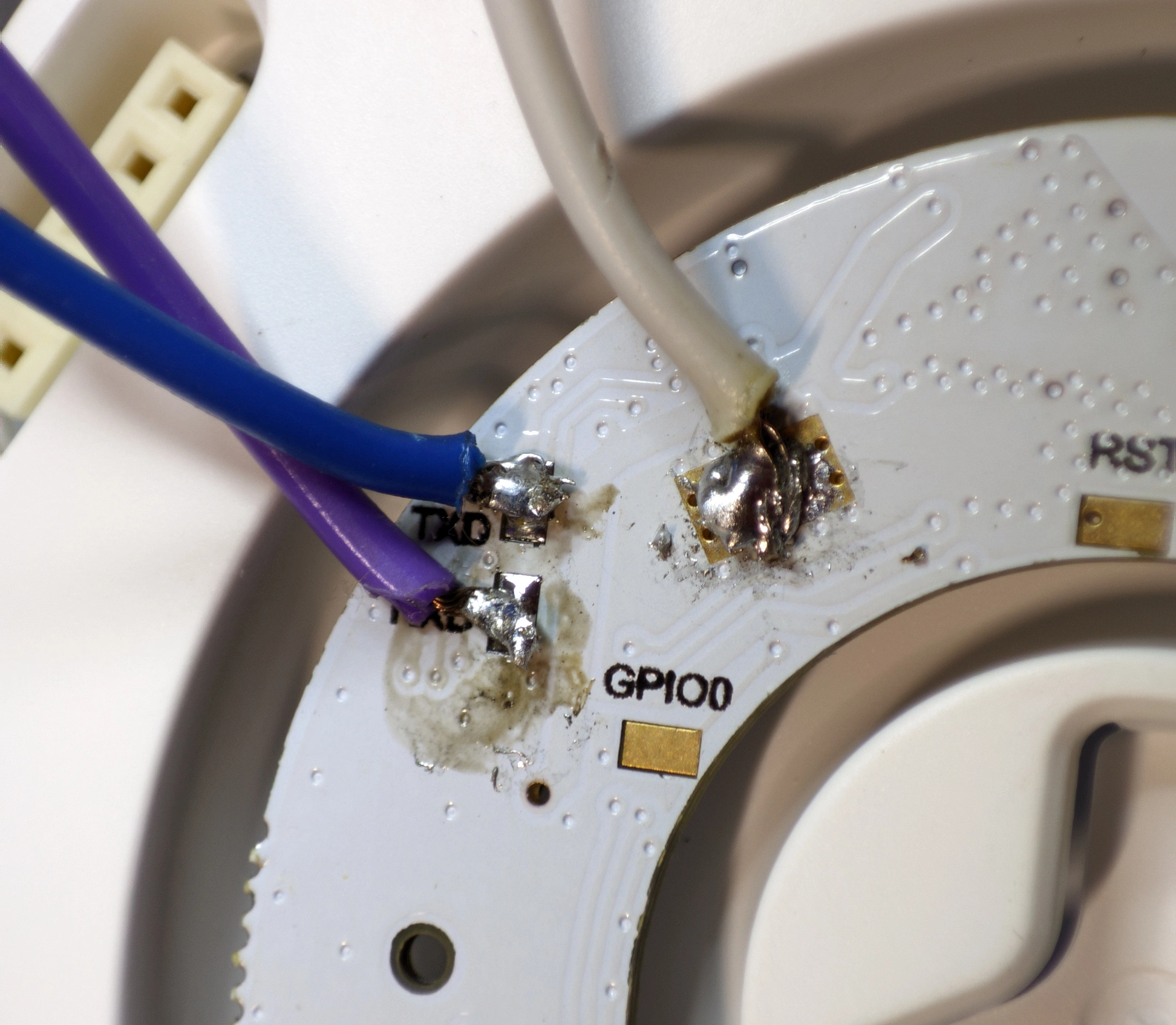
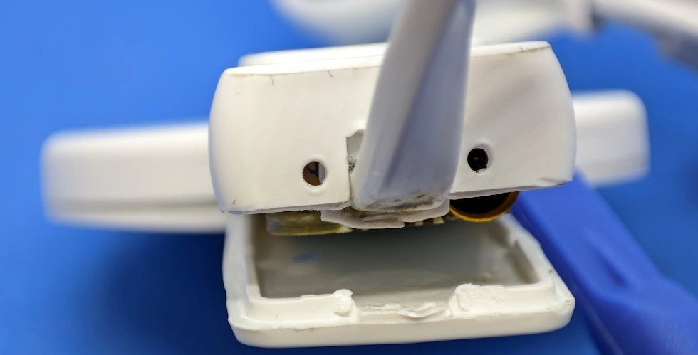
Use a prying tool or a spudger to separate back plate from the shell.
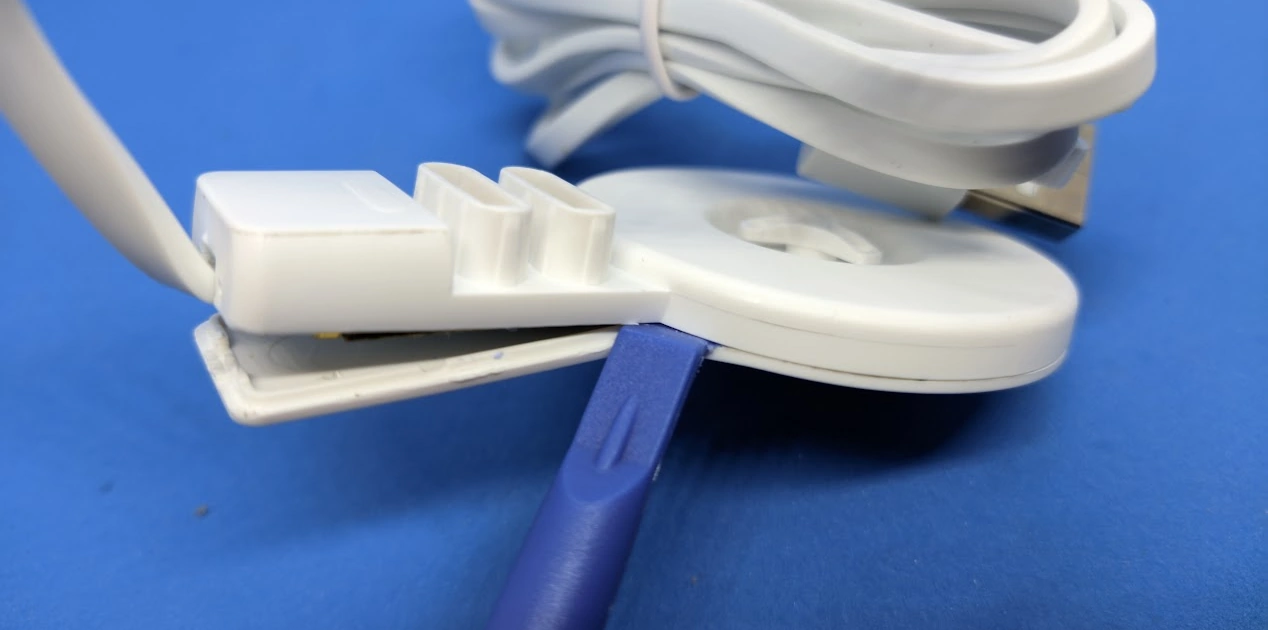
Take out the PCB, the flashing pads are located left of the ESP32 module.
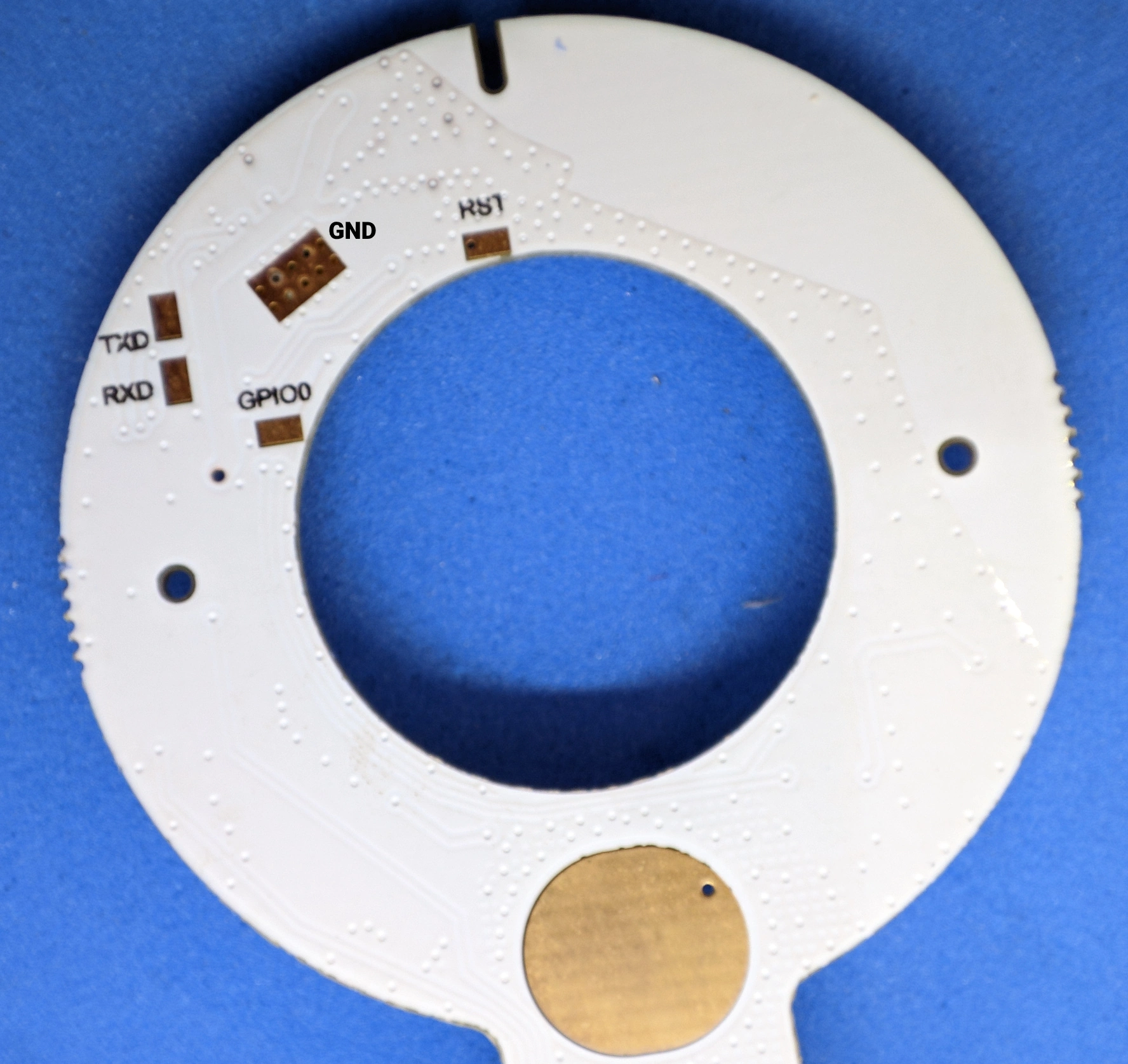
Connect your serial to USB adapter only to TX, RX and GND. Power the controller using its USB-C port.