


Available from:
Aliexpress.com
Aliexpress.com
Manufacturer:
Expo.tuya.com
Install method:
USB to Serial
| GPIO # | Component |
|---|---|
| GPIO00 | None |
| GPIO01 | Tuya Tx |
| GPIO02 | None |
| GPIO03 | Tuya Rx |
| GPIO04 | None |
| GPIO05 | None |
| GPIO09 | None |
| GPIO10 | None |
| GPIO12 | None |
| GPIO13 | None |
| GPIO14 | None |
| GPIO15 | None |
| GPIO16 | None |
| GPIO17 | None |
{"NAME":"Lightsensor","GPIO":[0,2272,0,2304,0,0,0,0,0,0,0,0,0,0],"FLAG":0,"BASE":54}
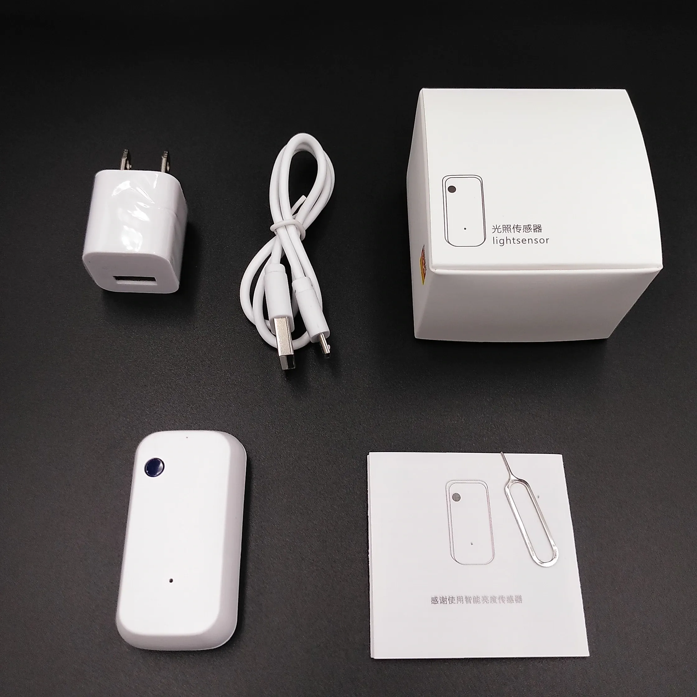
This is a Tuya USB powered illuminance sensor. Tiny power supply (US standard) and USB cable are supplied with the device.
Identified with MCU Product ID: {"p":"oedbumjmptbajtqz","v":"1.1.0","m":0}.
Flashing
Easily disassembled by removing the back plate, then prying away the PCB from the case.
The PCB is marked with “LS_V1.0 BY XP”. It runs on TYWE3S module and a secondary STM32F030F4P6 MCU.
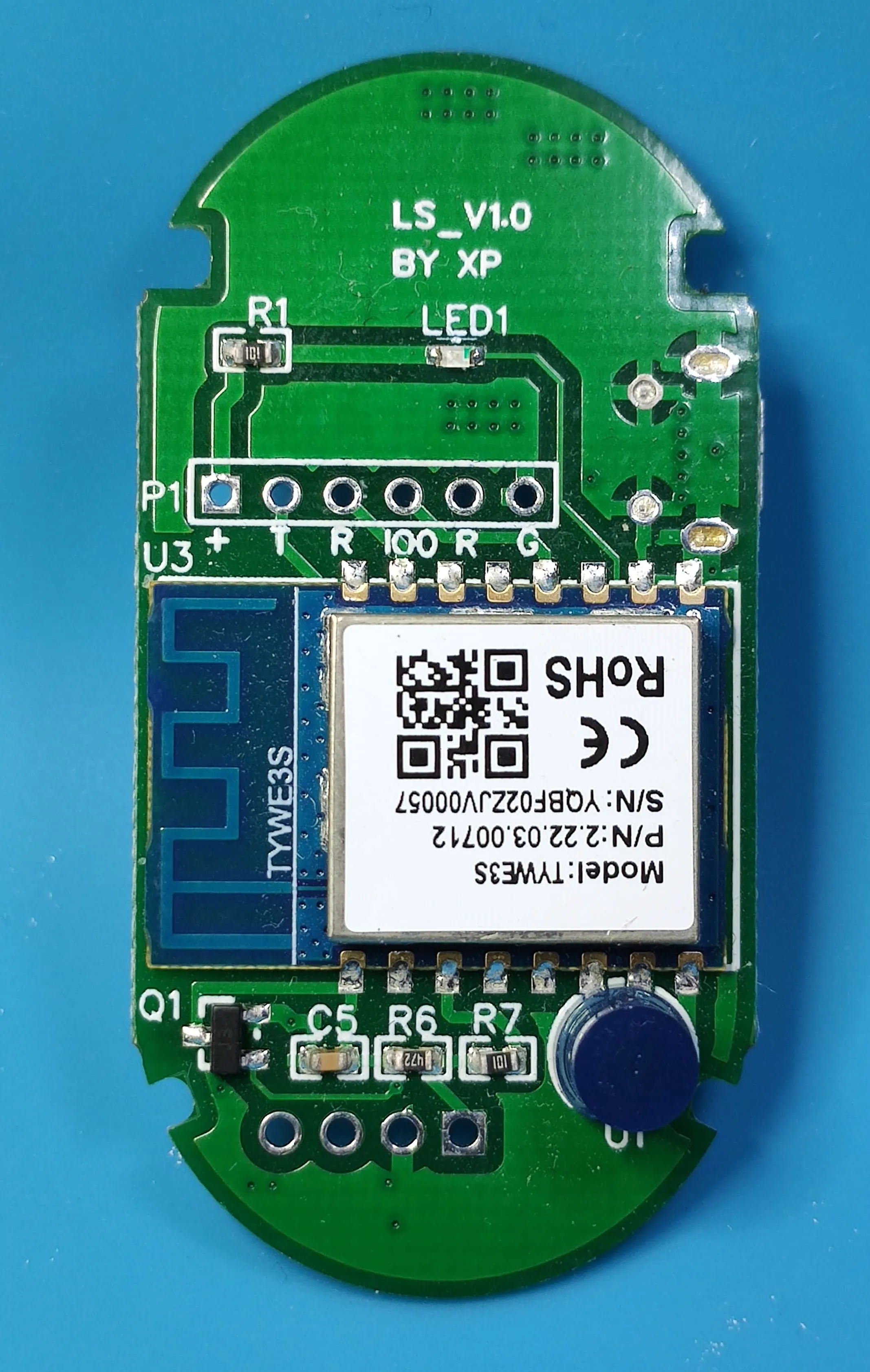
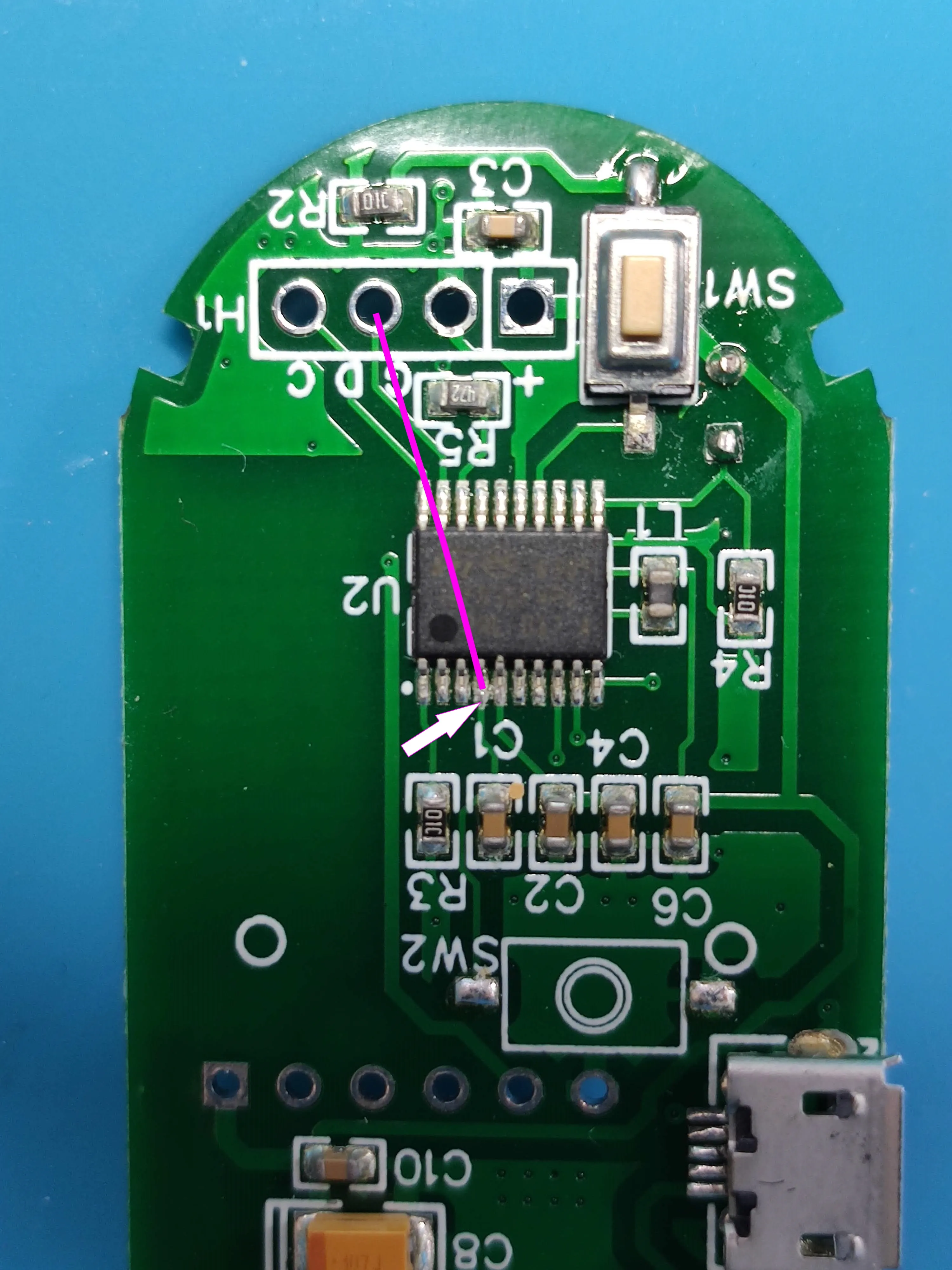
To flash the device connect to the 6 holes headers TX to R, RX to T, VCC to + and GND to G and IO0. R was likely supposed to be the RST pin for the STM32 MCU but it was not working in my case. Instead connect the 4th pin (marked on image) to GND during the flashing procedure (NOTE: the GND marked on the image is incorrect. A correct one is 3rd hole). Otherwise you will be unable to flash due to MCU interference
Configuration
After flashing Tasmota and configuring Wi-Fi and MQTT set Module 54 then issue
Backlog TuyaMCU 61,1; TuyaMCU 75,2; TuyaMCU 99,99
Illumination values will be visible in the webUI after a restart.
Features
dpId 1 is used for brightness state
0= low1= middle2= high3= strong
dpId2 is reporting illuminance in (according to instruction manual) lux.