


Available from:
Aliexpress.com
Amazon.com
Manufacturer:
Lilygo.cc
Install method:
USB to Serial
| GPIO # | Component |
|---|---|
| GPIO00 | User |
| GPIO01 | User |
| GPIO02 | User |
| GPIO03 | User |
| GPIO04 | I2C SCL 1 |
| GPIO05 | I2C SDA 1 |
| GPIO09 | None |
| GPIO10 | None |
| GPIO12 | Button 1 |
| GPIO13 | Button 3 |
| GPIO14 | Button 2 |
| GPIO15 | User |
| GPIO16 | User |
| GPIO17 | User |
{"NAME":"TTGO T12","GPIO":[1,1,1,1,608,640,0,0,32,34,33,1,1,1],"FLAG":0,"BASE":18}{"NAME":"TTGO-T12","GPIO":[255,255,255,255,5,6,0,0,17,19,18,255,255],"FLAG":15,"BASE":18}Hardware
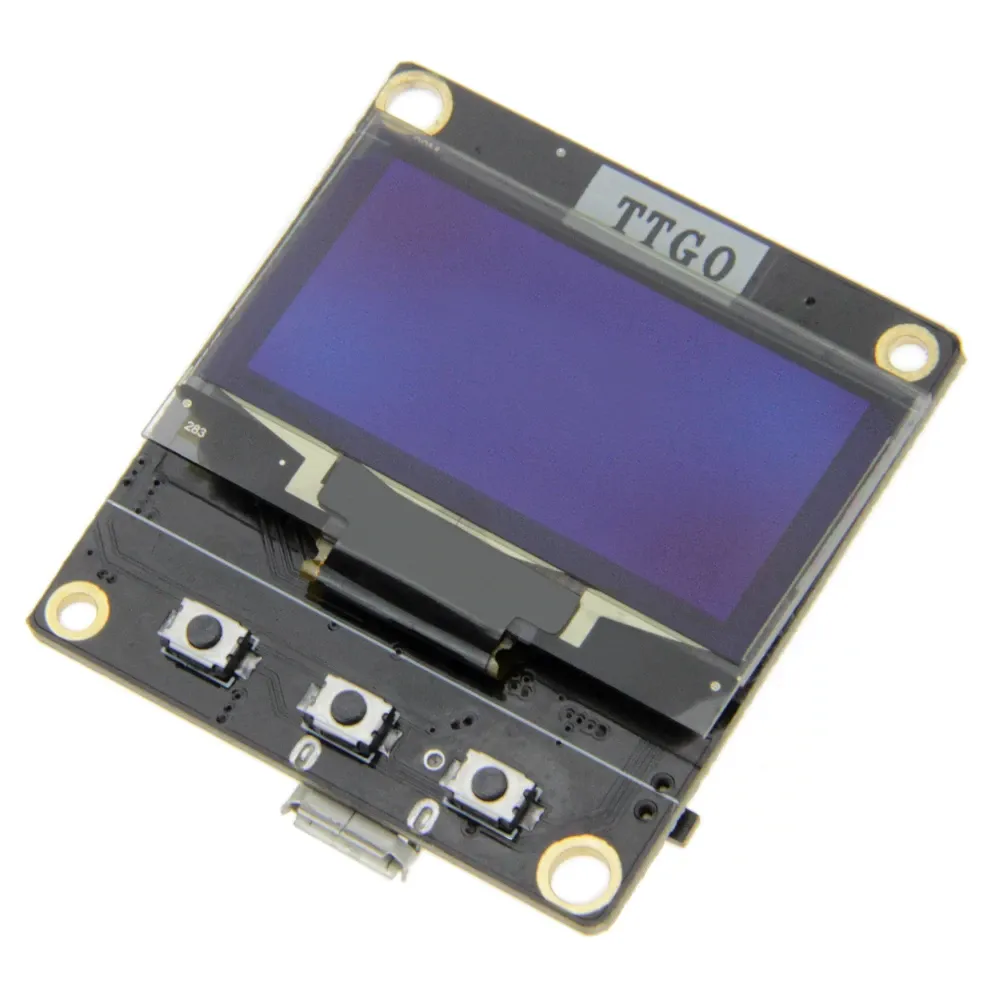
The LILYGO TTGO T12 is based on a ESP8266EX and has a SH1106 OLED display. It has 3 buttons on the front and a reset button.
The SH1106 display is connected to GPIO4 (SCL) and GPIO5 (SDA).
The buttons are connected to GPIO12, GPIO14 and GPIO13.
v1.0
This version has no logo on the front.
AliExpress
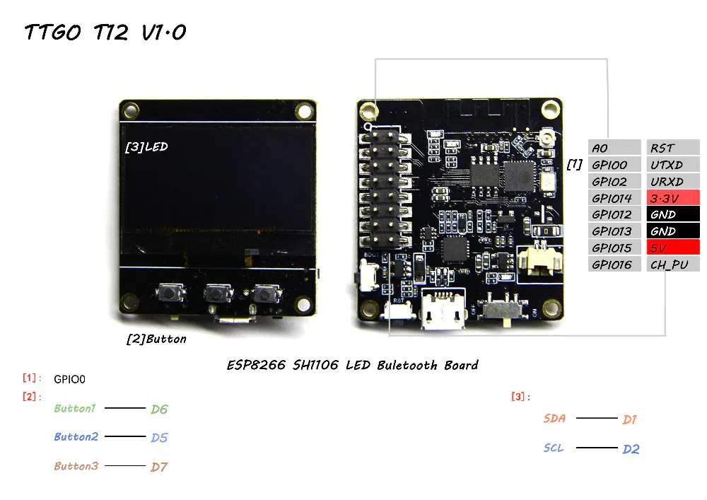
Pinout for version 1.0:
| Pin | Back Left, BOX Right | Back Right, BOX Left | Pin |
|---|---|---|---|
| 1 | A0 / GPIO17 | RESET | 16 |
| 2 | D3 / GPIO0 / FLASH | TXD / GPIO1 | 15 |
| 3 | D4 / GPIO2 | RXD / GPIO3 | 14 |
| 4 | D5 / GPIO14 / CLK / BUTTON2 | 3.3V | 13 |
| 5 | D6 / GPIO12 / MISO / BUTTON1 | GND | 12 |
| 6 | D7 / GPIO13 / MOSI / BUTTON3 | GND | 11 |
| 7 | D8 / GPIO15 / CS | 5V | 10 |
| 8 | D0 / GPIO16 / WAKE | CHIP_EN | 9 |
v2.0 / H214
Has a ““TTGO”” logo on the front. The product pages shows 2MB but it is actually has 4MB flash memory.
AliExpress
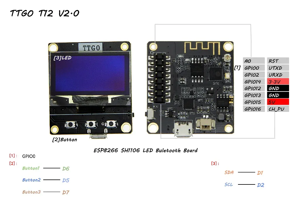
The pinout in the above image is not correct. This is the actual pinout for version 2.0:
| Pin | Back Left, BOX Right | Back Right, BOX Left | Pin |
|---|---|---|---|
| 1 | A0 / GPIO17 | RESET | 16 |
| 2 | D3 / GPIO0 / FLASH | TXD / GPIO1 | 15 |
| 3 | D4 / GPIO2 | RXD / GPIO3 | 14 |
| 4 | D5 / GPIO14 / CLK / BUTTON2 | 3.3V | 13 |
| 5 | D6 / GPIO12 / MISO / BUTTON1 | GND | 12 |
| 6 | D7 / GPIO13 / MOSI / BUTTON3 | D0 / GPIO16 / WAKE | 11 |
| 7 | D8 / GPIO15 / CS | 5V | 10 |
| 8 | Battery | CHIP_EN | 9 |
Check pauls_3d_things’s Blog fore more info
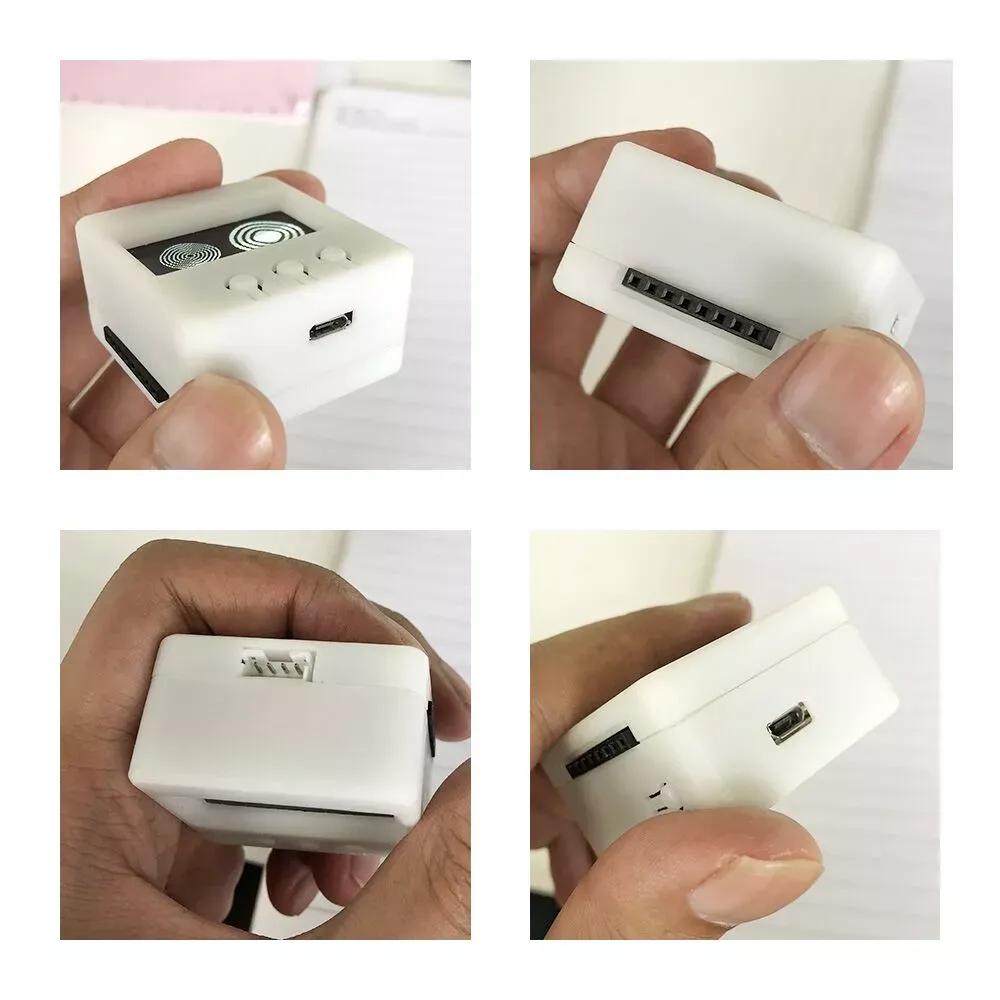
T-Hacker DIY BOX
Contains T12 v2.0 + accu in a case
AliExpress
Build Tasmota
You will need compile your own build of Tasmota with these options enabled in user_config_override.h:
#define USE_DISPLAY
#define USE_DISPLAY_SH1106
#define USE_I2C
Flashing
It is not possible to flash the module using the onboard micro-USB connection. You have to disconnect the USB power and use a 3.3V FTDI connection to the TXD, RXD, GND and 3.3V pins. You need to put the module in flash mode by following these steps:
- Connect pin 2 (GPIO0) to ground
- Press the RESET button
- Disconnect pin 2 from ground
You can use Tasmotizer the flash the module.
Configure Template
Template for Tasmota 9.1 and later
{""NAME"":""TTGO T12"",""GPIO"":[255,255,255,255,5,6,0,0,17,19,18,255,255],""FLAG"":15,""BASE"":18}
Template for Tasmota 9.0 or older
{""NAME"":""TTGO T12"",""GPIO"":[255,255,255,255,5,6,0,0,17,19,18,255,255,255],""FLAG"":15,""BASE"":18}
Configure Display
Enter in Console:
Backlog DisplayModel 7; I2cDriver 6; DisplayMode 5; DisplayDimmer 15; DisplayCols 21; DisplayRows 8