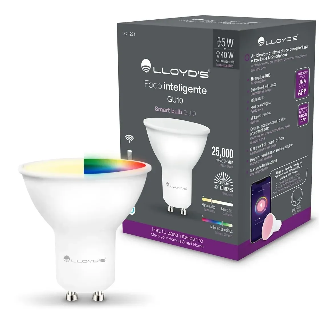
Available from:
Amazon.com.mx
Articulo.mercadolibre.com.mx
Manufacturer:
Lloydscorp.com
Install method:
USB to Serial
| GPIO # | Component |
|---|---|
| GPIO00 | Switch 1 |
| GPIO01 | None |
| GPIO02 | None |
| GPIO03 | None |
| GPIO04 | None |
| GPIO05 | None |
| GPIO09 | None |
| GPIO10 | None |
| GPIO12 | SM2135 DAT |
| GPIO13 | None |
| GPIO14 | SM2135 CLK |
| GPIO15 | None |
| GPIO16 | None |
| GPIO17 | None |
{"NAME":"LLOYDS LC-1271","GPIO":[160,0,0,0,0,0,0,0,4064,0,4032,0,0,0],"FLAG":0,"BASE":18}This bulb is tricky, since it uses the TYLC5 103 Chip which is a very small board. And it does not use PWMs for the leds, make sure you use the template correctly.
With the bulb disconnected from power, remove the translucent cover with a small knife or plastic spatula to not damage the cover. cut the white silicon around the PCB or plate with the leds and remove as much silicone as possible, then use some pliers or something to bend a clip as a hook so you can insert that hook and pull the board from the small hole located on the board. Be careful not to break or cut a cable sticking out from another hole, that’s the antenna.
Turn the bulb around with the legs sticking up towards you, if you have the GU10, you will see that there is a small hole in the center of the legs of the bulb, try sticking a small wire, you can use some DuPont cables or something stronger to try to push the board from within this holes and at the same time pull the board from the other side carefully so you wont break it.
Once it is out you’ll have to solder your cables to the TYLC5 103 chip, GPIO0, TX, RX, 3.3V, G, and use a USB to TTL adapter to flash tasmota with your desired tools. The GPIO0, TX and RX are on the back of the board and 3.3V and G are on the bottom of the board. If you are careful and with the correct soldering tip you can solder without burning anything else.
Put everything back together and Voila! you got your new tasmota GU10 bulb.


