


Available from:
Amazon.de
Install method:
USB to Serial
| GPIO # | Component |
|---|---|
| GPIO00 | Button1 |
| GPIO01 | None |
| GPIO02 | None |
| GPIO03 | None |
| GPIO04 | PWM2 |
| GPIO05 | PWM4 |
| GPIO09 | None |
| GPIO10 | None |
| GPIO12 | PWM1 |
| GPIO13 | None |
| GPIO14 | PWM3 |
| GPIO15 | None |
| GPIO16 | None |
| FLAG | None |
{"NAME":"ZX-2844-675","GPIO":[17,0,0,0,38,40,0,0,37,0,39,0,0],"FLAG":0,"BASE":18}This is new version of the Luminea ZX-2844 with a different board version. The GPIO configuration is completely different and there is no 3.3V pad. The 3.3V connection of the FTDI must be soldered directly to the ESP module.
Serial Connection
See the Hardware Preparation page for general instructions.
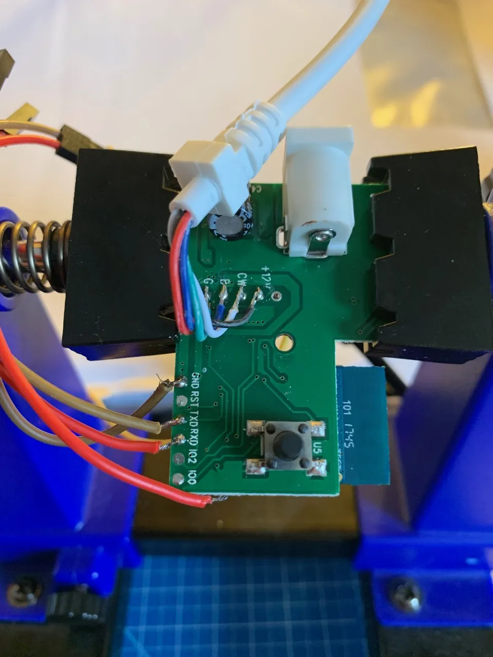
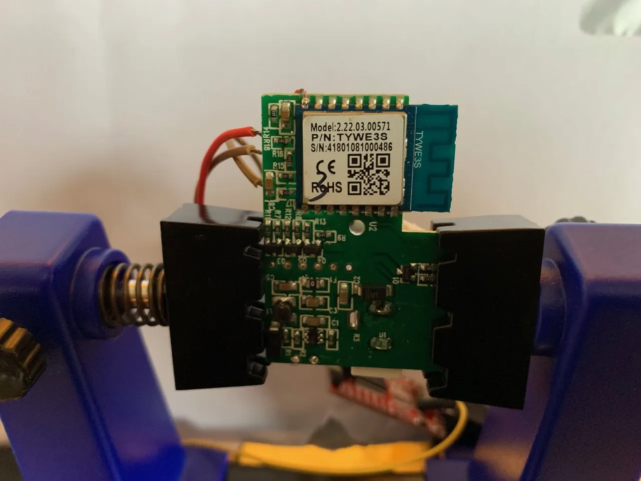
The serial header (RXD, TXD, GND) as well as GPIO0, GPIO2 and RESET (IO0, IO2, RST) are populated as test pads on the frontside of the PCB. Unfortunately the 3.3V is not available any more, so you have to solder it directly on the ESP chip pin (see second image). You can easily add some solder to fix the wires during the flash process.
To place the board into flashing mode, you will need to short IO0 to GND. This can remain shorted while flashing is in progress, but you will need to remove the short in order to boot the Tasmota firmware.